Why One Cooling Slot Can Undo a Mission Computer's Shielding
The Box Is the EMC Design
A multi-core mission computer is a broadband radio transmitter that happens to also run software. Processor clocks and their harmonics, DDR memory strobes, gigabit Ethernet, and switching power supplies fill the spectrum from megahertz to several gigahertz. One detail from the design-review folklore is worth repeating: the 63rd harmonic of a standard 25.000 MHz Ethernet crystal lands at 1,575.000 MHz — 420 kHz from the center of GPS L1, inside the main lobe of the signal a receiver is trying to hear at around −158 dBW, some 20 dB below thermal noise. That fragility is why DO-160's radiated-emission limits carve protected notches around the GNSS bands, about 10 dB deeper than the neighboring limit for standard cabin equipment and 15 dB deeper for equipment in view of the antennas.
Between all that digital noise and the aircraft's radios stands one part: the aluminum box. Solid aluminum is effectively opaque here — the skin depth at 1 GHz is 2.6 µm against a 3 mm wall. Real enclosures leak where the metal is interrupted: vents, seams, and connector penetrations. So the interesting engineering question is not "does shielding work" but "what does each opening cost" — and that is a question you can put numbers on.
Five Versions of the Same Computer, One Number Each: Shielding Effectiveness
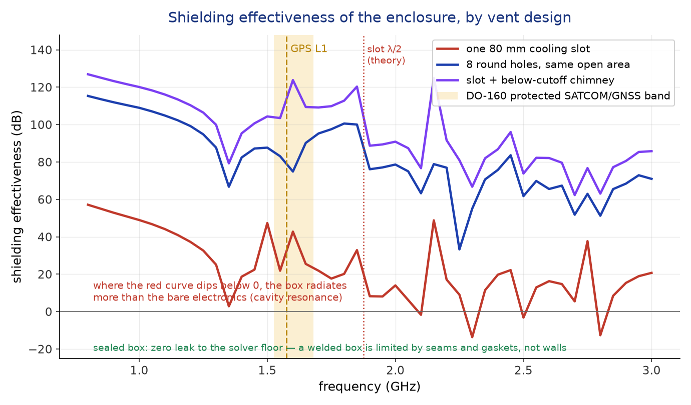
We modeled a generic half-ATR-style conduction-cooled chassis — 124 × 194 × 320 mm, 3 mm aluminum walls, the classic finned flanks and 38999-style front panel — and placed a small broadband dipole inside as a stand-in for the noisy electronics. Five HFSS solves, 0.8–3 GHz: the bare source with no enclosure (the reference), the box welded shut, the box with one 80 × 3 mm cooling slot in the lid, the box with eight 6 mm round holes whose open area matches the slot's, and the slot again with a ribbed below-cutoff chimney over it — the home-made cousin of a honeycomb EMI vent. Shielding effectiveness is the honest ratio used in the enclosure-shielding literature: the field radiated with the enclosure versus the same source with no enclosure at all, frequency by frequency.
One Slot Is an Antenna
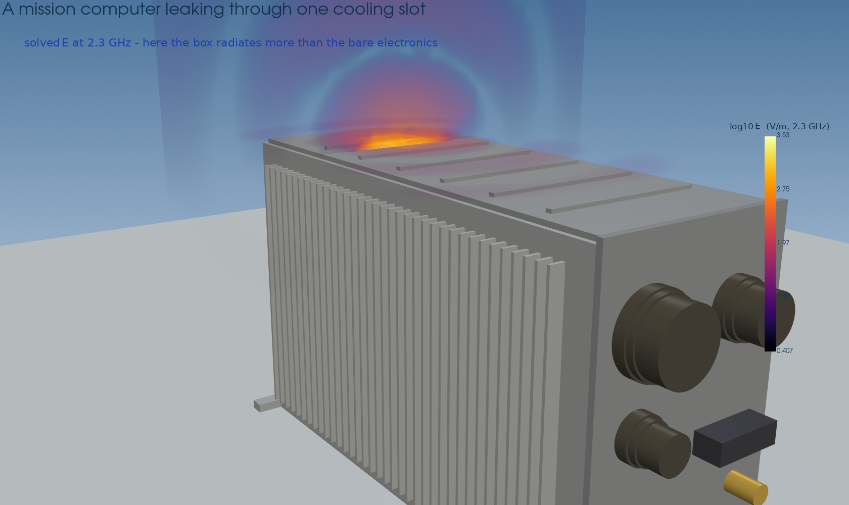
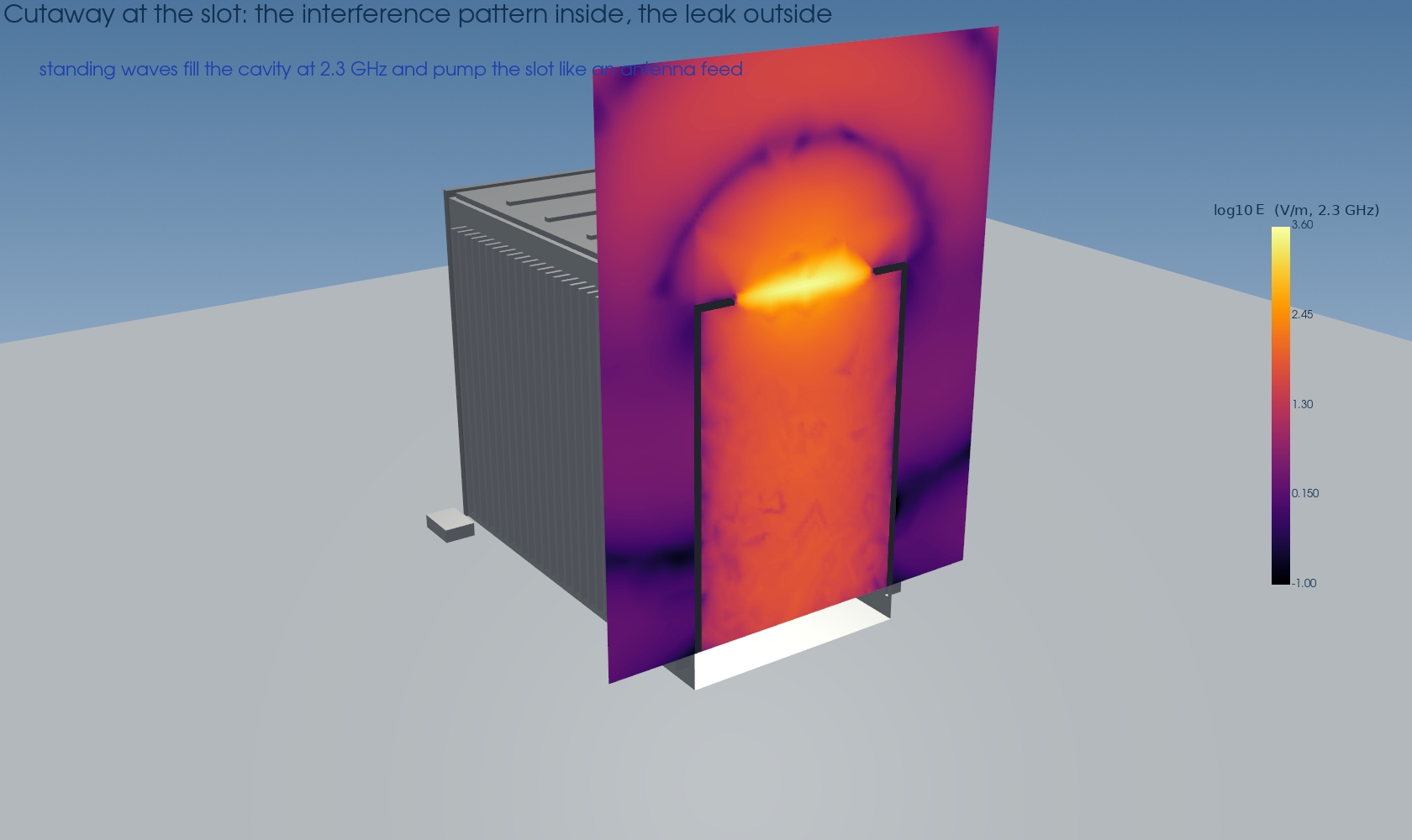
A narrow slot in a conducting wall is a slot antenna — the Babinet complement of a dipole. Below resonance it leaks in proportion to its longest dimension; at the half-wave frequency, f = c/2L — 1.875 GHz for our 80 mm slot — it radiates about as well as a purpose-built antenna of the same size. The solve shows exactly that collapse: 57 dB of shielding at 0.8 GHz eroding to roughly 20 dB through the resonance region. It also shows what the hand formula cannot: the slot does not act alone. It couples to the resonant modes of the cavity behind it, and the worst point lands at 2.30 GHz — a slot–cavity hybrid — where shielding reaches minus 13.7 dB. At that frequency the "shielded" computer out-radiates the same electronics sitting in free air, the box working as a resonator that collects the interior field and feeds it to the slot. That counterintuitive sign flip is a documented behavior of enclosures near cavity resonance in the shielding literature, and it is precisely the kind of thing that only shows up in a full-wave solve.

Same Open Area, Very Different Leak
The eight-hole variant is the free lunch of EMC design. Its open area matches the slot's within a few percent — the airflow argument is a wash — but each 6 mm hole is electrically tiny, and small-aperture leakage falls with the sixth power of aperture size. The penalty for using several holes grows only as 10 log₁₀N. Net: at GPS L1 the hole field shields 79 dB against the slot's 32 dB, and at the slot's resonance the gap is 68 dB. Even at the nasty 2.25–2.3 GHz cavity mode, the holes hold 33 dB where the slot went negative. And when the airflow budget genuinely demands the full slot cross-section, depth does what diameter cannot: the 12 mm ribbed chimney turns each cell into a waveguide operating far below cutoff, whose attenuation the classic 27.3 · depth/width rule puts at +36 dB — the solve delivers that and more, holding above 100 dB through the GNSS band. Commercial honeycomb vent panels are this exact trick, mass-produced.
Then We Filled the Box: Five Sources and a Victim
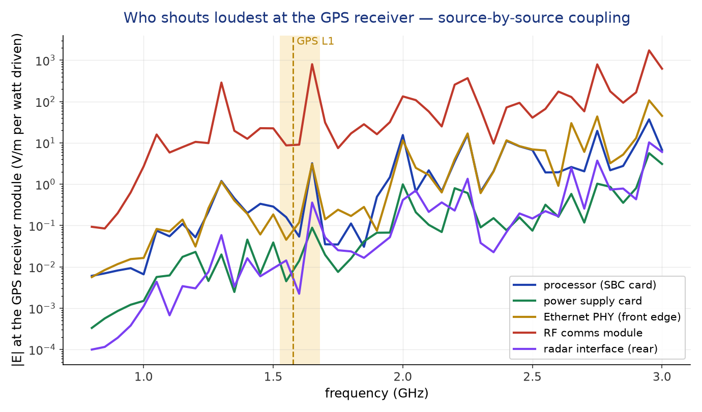
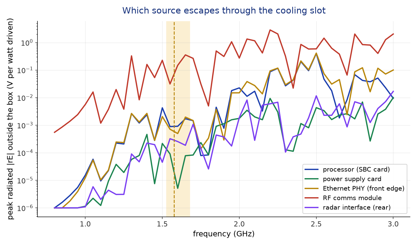
A shielding number answers what escapes. The other half of the original question is what happens between the modules locked inside together — so we populated the enclosure: a backplane and four 3U cards on standard 25.4 mm pitch, and five independent broadband transmitters placed where the real offenders live. The processor sits mid-card on the SBC; the Ethernet PHY at the SBC's front edge; the RF comms module on card three; the power electronics and the radar interface mounted with their radiating structures turned 90° — different positions and different polarizations. The GPS receiver becomes what it really is in this drama: the victim — a field probe at its module position just behind the front-panel antenna feedthrough. One 232,000-tetrahedron HFSS solve carries all five ports at once, and because the physics is linear, each source can be switched on alone afterward without re-solving.
What This Covers — and What a Full Campaign Adds
The community request named the whole EMI/EMC problem: interference between processors, power electronics, Ethernet, RF modules, GPS receivers, and radar interfaces inside a compact enclosure, plus shielding effectiveness, PCB stack-up, cable routing, and enclosure design. This study now covers the box-level levers end to end: enclosure design and shielding effectiveness priced across four vent designs, and module-to-module interference solved directly — five sources at their card positions, the GPS receiver as the measured victim, a full coupling hierarchy out of one solve. The two remaining levers are their own solves in the same toolchain, and we have run each on this blog: PCB stack-up and power-delivery noise is a SIwave study (why a board browns out without its decoupling capacitors), and cable/harness parasitics — the paths that carry noise out through the 38999s past any shield — are a Q3D study (why a charging cable gets warm). A certification-grade campaign chains all three; this post prices the box and everything inside it.
So — Does the Mission Computer Pass?
This is the shape of an EMI/EMC validation campaign compressed to its essence: the same product, several enclosure decisions, each priced in decibels before any hardware exists. The slot version of this box would be a certification risk anywhere near a GNSS antenna; the hole-field version costs nothing to manufacture and buys ~47 dB at the frequency that matters most; the chimney buys margin that looks like a sealed box while still passing air. History says this is worth doing early: from the docked laptop correlated with autopilot disconnects in 1995 to the 2014 airworthiness directive that replaced cockpit displays on some 1,300 aircraft after Wi-Fi-band interference blanked them during testing, aircraft-level EMI surprises are expensive precisely because they arrive late.
Designing an enclosure, a vent pattern, or a chassis that has to live next to a GPS antenna? The decibels are decided in CAD, long before the test chamber — and a full-wave solve prices every slot, hole, and seam before you cut metal. We run EMI/EMC shielding studies in Ansys HFSS, geometry through certification-ready evidence. Rand Simulation — innovation through insight.