How a Solid Motor's Grain Shape Sets Its Thrust Curve
A liquid engine has valves; you can throttle it. A solid motor is a casting of rubbery propellant with a hole down the middle, lit at one end of the hole. Once it is burning there are no moving parts and no control — the thrust-versus-time curve is decided entirely by geometry. That is why the shape of the hole, the grain, is the single most important design choice in a solid motor, and why the same motor case can be a booster or a sustainer depending only on how the propellant is cut.
The chain is short and unforgiving. Propellant burns back normal to its surface at a rate that rises with pressure (St. Robert's law, r = a Pcn). The gas it makes has to leave through a fixed throat, and that balance sets the chamber pressure: more burning area means more gas means higher pressure. Thrust then rides on chamber pressure through the nozzle. So the burning area as the grain burns back — which is pure geometry — writes the thrust curve.
There is a stability catch hidden in that burn-rate law, and it is why the pressure exponent n matters as much as the geometry. The chamber pressure sits where the gas generated equals the gas leaving, and that balance is only stable if n < 1. Below one, a small pressure bump burns propellant a little faster but chokes off through the throat even faster, so the pressure settles back down. At or above one the loop runs away and the motor over-pressurizes. Real propellants are formulated to sit around n = 0.3–0.5 for exactly this reason, and it is the same exponent that decides how sharply the grain-shape effects below translate into pressure — a low exponent softens them, a high one exaggerates them. The value used here (n = 0.35) is representative of a composite propellant.
Solving the motor, not just its nozzle
To get thrust honestly you have to solve the flow. This study builds the 500 mm-long port and the convergent-divergent nozzle as an axisymmetric grid, injects the grain's gas as a hot mass source, and lets Ansys Fluent solve the compressible flow — the gas accelerating down the port, choking at the throat, and expanding supersonically through the bell. The chamber pressure and the thrust are read directly from the solved field.
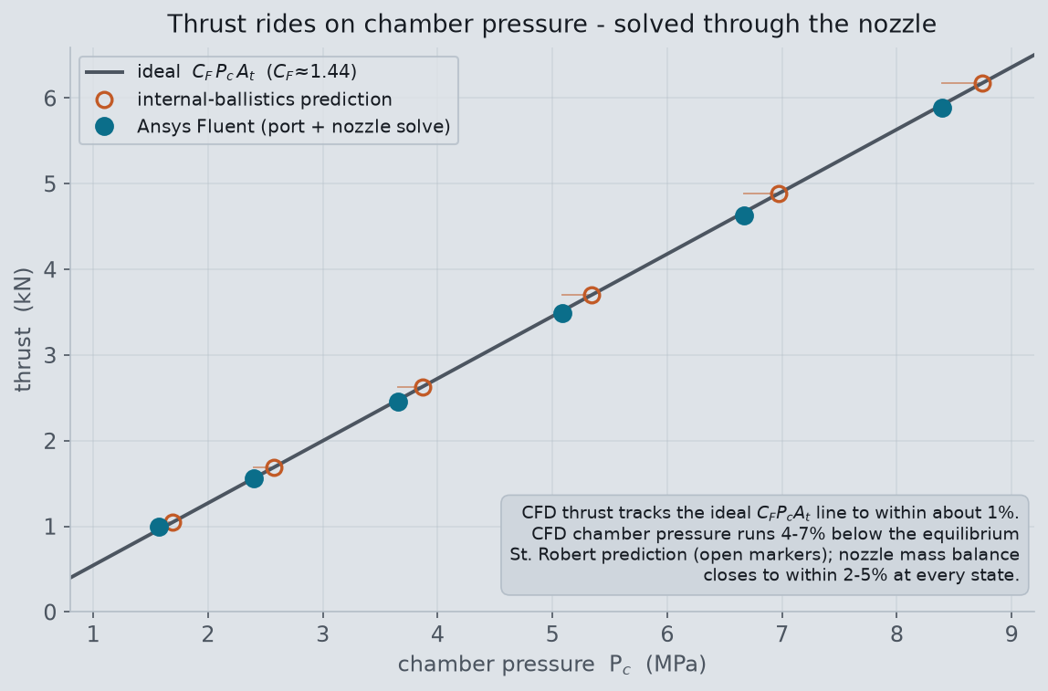
The CFD lands on the ideal thrust-coefficient line to within about 1% across the whole burn, and the mass leaving the nozzle matches the mass injected at the grain to within a few percent. The chamber pressure it predicts runs 4–7% below the closed-form equilibrium value — the difference between a lumped-parameter estimate and a resolved internal flow, and exactly the kind of margin the solve exists to find. With a nozzle model that is trustworthy, the grain-shape comparison becomes a fair one: the only thing that changes between the families is the burning-area history, exactly as in a real motor.
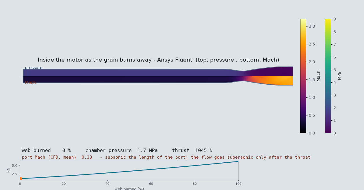
The port flow is where a real design risk shows up that a lumped estimate misses. Early in the burn the port is narrow and all the gas the grain is making has to squeeze down it toward the throat; if the port is too small the flow speeds up, scrubs the burning surface, and drives it faster than the pressure law alone predicts (erosive burning), which can spike the early pressure and, in the worst case, crack the grain. Sizing the port to a port-to-throat area ratio of 2.0 at ignition keeps that in check: the solved port Mach peaks at about 0.33 and falls as the port opens, so the motor breathes freely at every state.
| web burned | port dia (radius) | port / throat area | port Mach (ballistics) | port Mach (Fluent) |
|---|---|---|---|---|
| 0% | 34 mm (17 mm) | 2.0 | 0.31 | 0.33 |
| 18% | 46 mm (23 mm) | 3.7 | 0.16 | 0.17 |
| 36% | 58 mm (29 mm) | 5.8 | 0.10 | 0.11 |
| 58% | 72 mm (36 mm) | 9.0 | 0.07 | 0.07 |
| 79% | 86 mm (43 mm) | 12.8 | 0.05 | 0.05 |
| 100% | 100 mm (50 mm) | 17.4 | 0.03 | 0.04 |
Four grains, four thrust curves
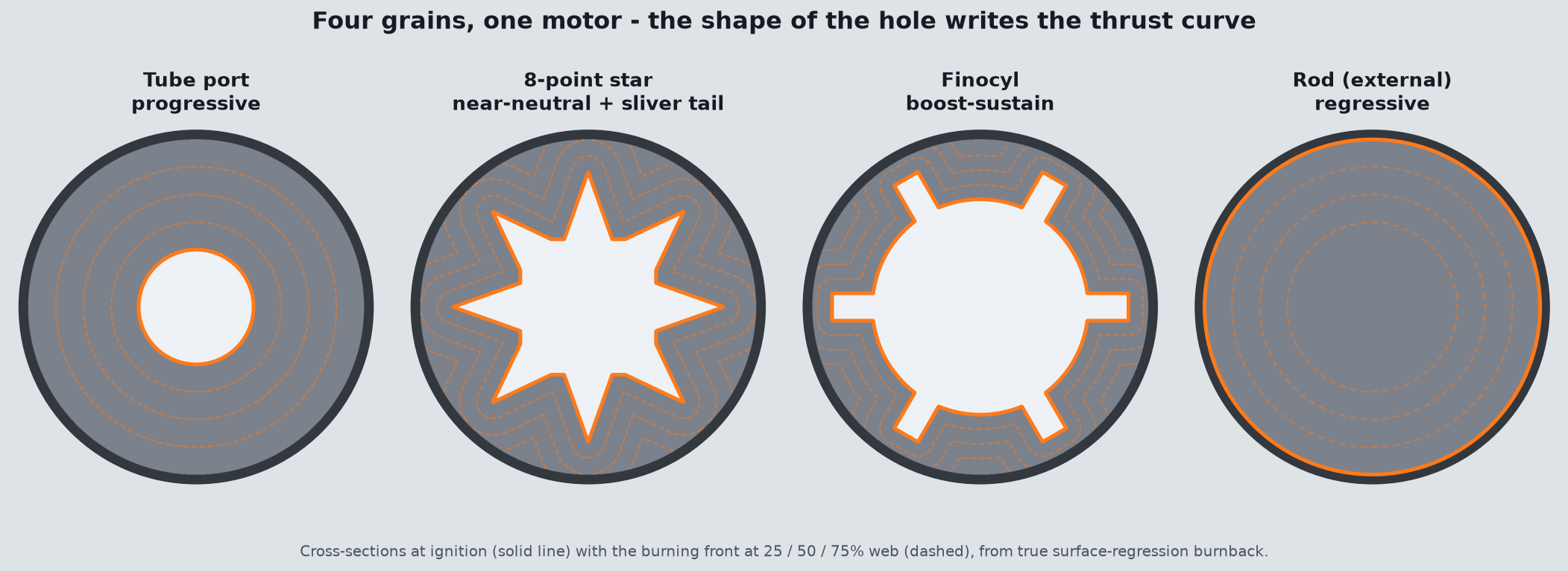
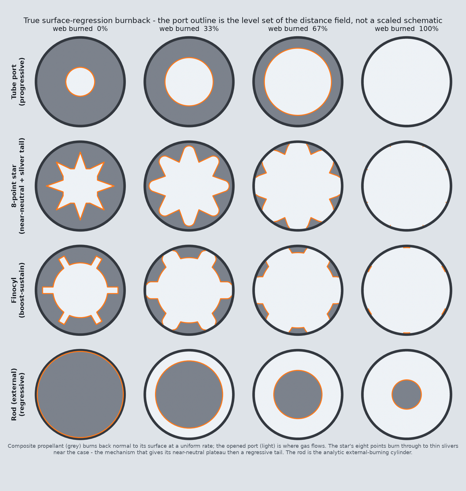
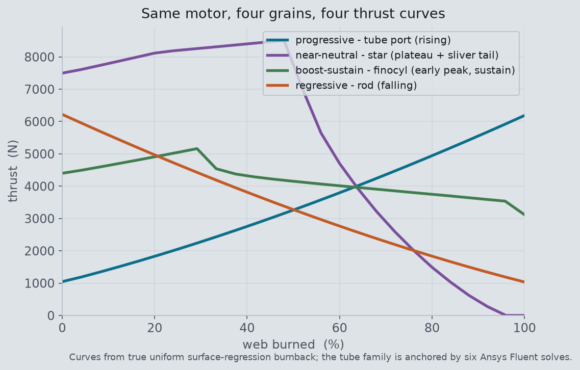
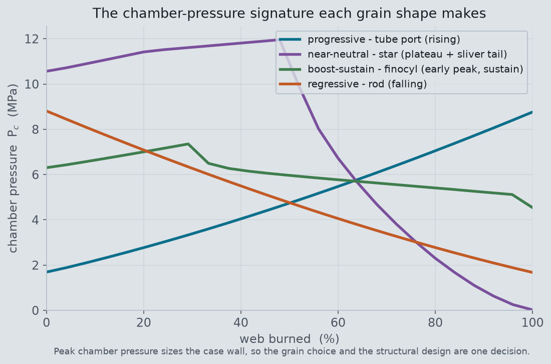
These are the archetypes rocket designers actually reach for. Want a booster that comes off the pad hard and eases as the vehicle lightens? That is a regressive grain. Want a sustainer that holds roughly steady thrust for a long coast? Cut a star: it runs a broad near-neutral plateau — chamber pressure holding within about ±13% across the first half of the burn — before its points burn down to slivers and the trace tails off. Want a hard kick that then settles to a cruise? A finocyl gives an early boost as its fins burn out, then a lower sustain on the growing bore. Want to trade a soft start for a strong finish? A progressive port does that.
What the grain shape controls is when the impulse is delivered and how much burning area is exposed to make it. Cut the propellant to expose more surface at once and the motor runs harder and briefer; spread that surface out across the burn and it runs softer and longer. The star here exposes the most perimeter and runs at the highest chamber pressure of the four; the rod exposes its whole outer surface first and then only shrinks. The chamber-pressure signatures below tell the same story as pressure — and pressure is what sizes the case wall, so the grain choice and the structural design are the same decision.
One parametric motor, six solves
The motor was built parametrically and swept through six burnback snapshots in Fluent, each solve checked against the internal-ballistics law and the mass balance before it was trusted. From that one validated nozzle model, the four grain families' thrust curves follow from their burning-area histories. That is the everyday value of scripting the solver: turning “grain shape matters” into four thrust curves an engineer can pick a mission from.
What the review changed — and what it didn’t
A propulsion engineer who read the original post flagged the initial port sizing and the schematic burnback. They were right, and this revision replaces both. What changed:
- Port resized so nothing chokes in the port. The port now opens at a 34 mm diameter (17 mm radius) against the 24 mm throat — a port-to-throat area ratio of 2.0 at ignition, up from 1.56. To be clear about the original: the on-screen "15 mm" was a radius, so the first port was 30 mm in diameter — larger than the 24 mm throat, not smaller — and the flow never actually choked in the port. But 1.56 was tighter than good practice, so we opened it up, and every figure now labels radius versus diameter explicitly. The solved port Mach peaks at about 0.33 at ignition and falls through the burn (table below).
- True surface-regression burnback. The original cross-sections were schematic radial offsets. The burning surface is now the level set of a distance field measured from the initial port — the grain burns back normal to itself at a uniform rate — so slivers and tip burnout emerge from the geometry instead of being assumed.
- Corrected star and finocyl signatures. The schematic-burnback simplification produced non-physical signatures. Recomputed from the true regression, the star now holds a broad near-neutral plateau and then falls away as its points burn down to slivers, and the finocyl shows a genuine early boost before its sustain — matching the labels the shapes actually earn.
- Port length wording. The 500 mm figure is the axial length of the port, not a diameter; it now reads "the 500 mm-long port" everywhere.
What we checked and kept: the thrust numbers. The review prompted a recheck of the thrust coefficient, and it stands. For this 4:1 bell at γ = 1.2 the ideal CF computes to about 1.44 (the isentropic momentum term; the nozzle is near perfectly expanded at the design point), and the study's thrust tracks CF Pc At as stated. A CF of 0.8–1.0 is not the coefficient for a converging–diverging nozzle at this expansion ratio. We did add a note that real nozzles lose 2–5% to divergence and friction, so delivered thrust runs a few percent below ideal; the two thrust figures quoted in the original (1513 and 1526 N at the same state) were the CFD-integrated value and the closed-form ideal, which agree to about 1%. Across the burn the Fluent thrust tracks the ideal line to within about 1%, with chamber pressure sitting 4–7% below the equilibrium St. Robert prediction and the nozzle mass balance closing at every state. These corrections are now part of the system's internal-ballistics rules, so every future motor study starts from them.
Designing a motor, a gas generator, or anything where an internal flow chokes through a nozzle? The chamber pressure and thrust are a solve, not a spreadsheet guess, and the grain that hits your mission is a geometry sweep. We do internal-ballistics and nozzle CFD in Ansys Fluent. Rand Simulation — innovation through insight.