How Hot a Brake Disc Gets on a Long Mountain Descent
Going down a long grade, the brakes do something they never do on the flat: they turn potential energy into heat without stopping. A 2200 kg vehicle held at 100 km/h down a 12% grade is shedding altitude the whole way, and every watt of that has to leave through four brake discs. Split to the front axle, it is roughly 23.4 kW into each front rotor — the heat output of a dozen electric kettles, dumped into a thirteen-kilogram ring of iron, minute after minute. The question a brake engineer has to answer is simple to ask and easy to get badly wrong: how hot does it actually get, and does the disc survive it?
Three estimates, a thousand degrees apart
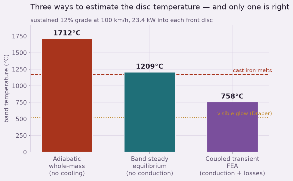
Reach for the simplest estimate first: take the whole descent's heat, spread it evenly through the disc's mass, and assume nothing escapes. That adiabatic bound gives about 1710 C — well above the melting point of cast iron, which would say the rotor is a puddle before you reach the valley. It is wrong because it ignores every path the heat takes back out.
So swing the other way: assume the rubbing band reaches a steady balance, shedding heat as fast as it arrives by convection to the passing air and radiation from its glowing face. That gives about 1210 C — lower, but still essentially at the melting point, and still alarming. This estimate is closer to the physics but makes its own mistake: it treats the thin band as an island, ignoring that it is welded to a much larger, cooler disc that quietly conducts heat away from it.
Put conduction back in and solve the temperature field in time, and the answer drops to about 758 C. That is hot enough to glow a healthy cherry-red — the disc absolutely does light up on a hard alpine descent — but it is a temperature gray iron lives at, not one it melts at. The three estimates span nearly a thousand degrees, and the difference between them is not academic: two of them condemn a disc that is fine. The only way to know which story is true is to let the heat move where it really goes.
Why the surface runs so far ahead of the bulk
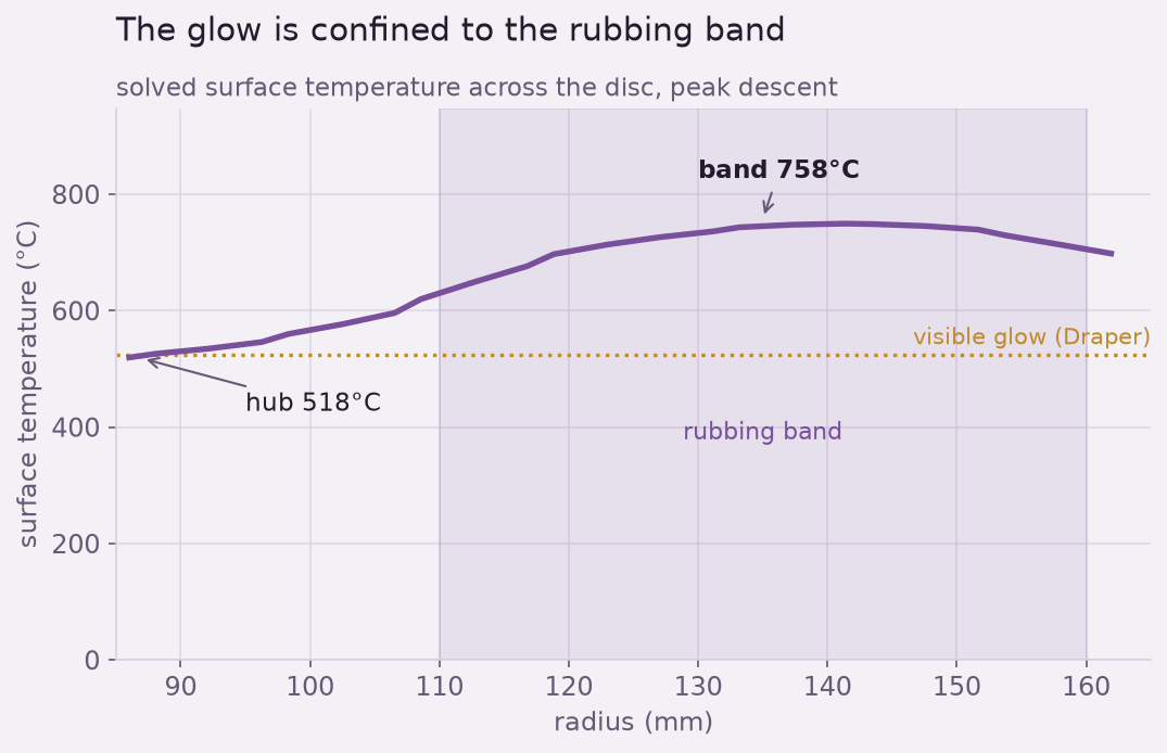
The reason the band and the hub can differ by hundreds of degrees is that cast iron is a mediocre heat conductor (about 50 W/m·K). Heat is pumped into the thin rubbing band far faster than the disc can spread it inward, so the band's surface races ahead of the disc's bulk. This is the same penetration effect that lets you brush a finger through a candle flame: the energy is intense but has not had time to soak in. On the disc it means there is no single “disc temperature” to quote — there is a hot ring and a cool center at the same instant, which is exactly what the solved field and the glow render show.
It also means the answer is inherently transient. A five-minute descent is long enough for the band to climb toward its glowing plateau but not long enough for the whole disc to catch up, and a solver that marches the temperature field forward in time is the only tool that captures both the fast surface and the slow core at once. That coupling — heat in at the band, heat out by convection and radiation, heat conducted inward to the hub — is the physics the two hand estimates each got half right.
The stress you cannot see: heat checking and coning
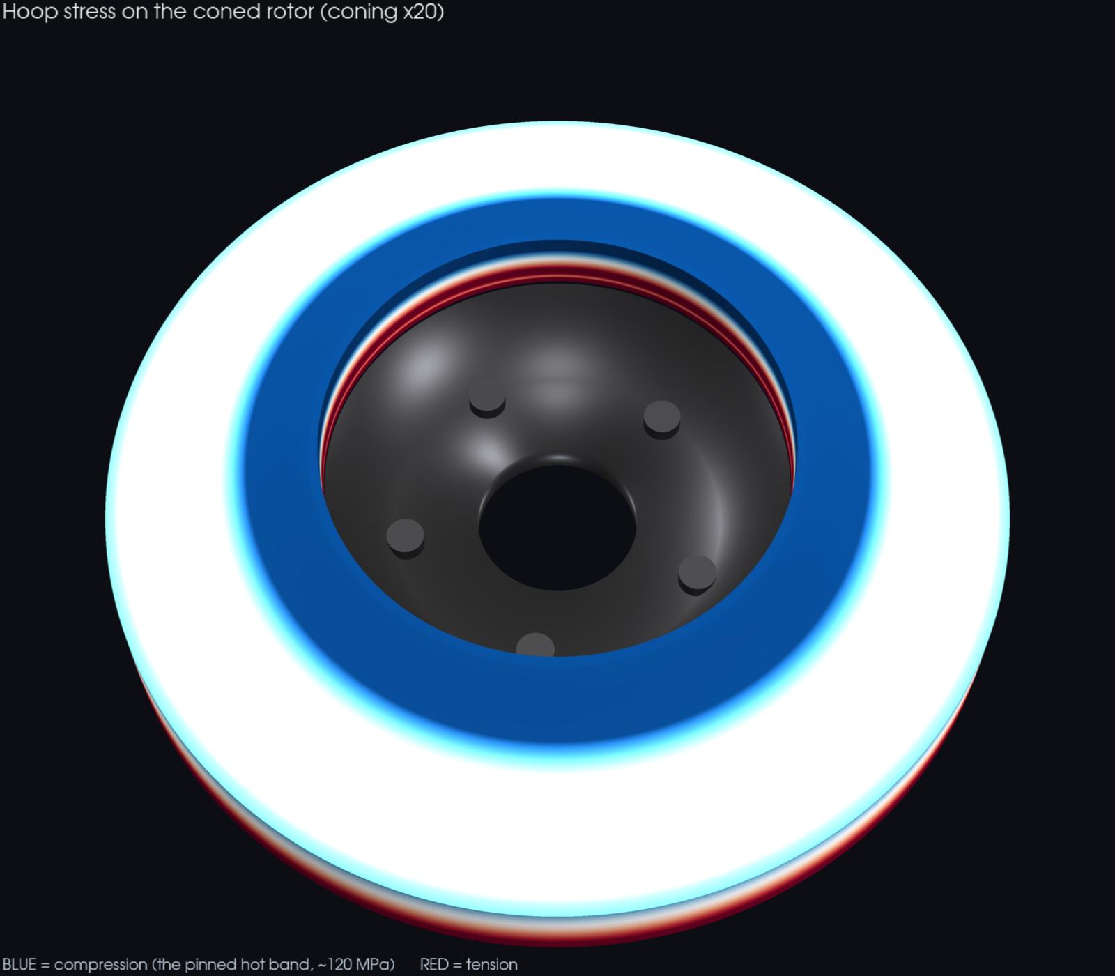
Temperature is only half of it. Feed that 758-to-518 C field into a stress solve and the gradient does mechanical work. The hot band wants to grow, but the cooler iron on either side of it will not let it — so the band is forced into circumferential (hoop) compression, on the order of 120 MPa here, with sharper local peaks. Cast iron shrugs off compression; it is several times stronger in compression than in tension. So one descent does not crack a rotor.
The damage is cyclic. Every hard, sustained stop drives the band hot and into compression; every cool-down reverses it, leaving the surface in residual tension against a material whose tensile strength is only about 250 MPa. Do that a few hundred times and the friction face crazes into the fine web of radial cracks every mechanic recognizes as heat checking. The single-descent solve is what gives you the stress amplitude that drives that fatigue — the quantity you cannot get from a temperature number alone.
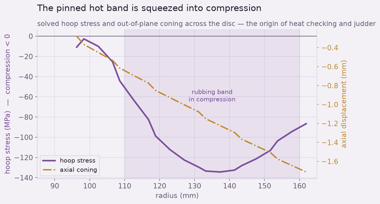
The other structural consequence is coning. Because the disc is hotter and more expanded at its rubbing band than at its bolted hub, it dishes out of flat — roughly 1.4 mm on this abusive descent. A coned disc no longer meets the pads squarely; its effective thickness varies around and across it, and that variation is felt through the pedal and the wheel as the low-frequency shudder of brake judder. The same solved displacement field that tells you the disc survives thermally also tells you it will not run smooth.
Automation is the point
The disc was built and meshed once, the descent's heat load computed from the vehicle and the grade, and the whole chain — transient thermal solve, then a sequential thermal-stress solve on the same mesh — run unattended in Ansys Mechanical, with the results checked against hand anchors at every step: the band-balance temperature, the melting point, the Draper glow threshold, the constrained-expansion stress. The output is not one picture but a design tool: change the vehicle mass, the grade, the disc thickness, or swap gray iron for a vented or carbon-ceramic rotor, and the same script re-runs the story and tells you the new peak temperature, the new stress amplitude, and the new coning. Turning “it glows and eventually cracks” into “23.4 kW gives you 758 C, 120 MPa, and 1.4 mm of cone” is the everyday value of scripting the solver.
Sizing a rotor, a clutch, an exhaust component, or anything where a thermal gradient becomes a stress? The surface and the core run on different clocks, and the gradient between them is where parts glow, crack, and warp — it is a coupled solve, not a single temperature. We do transient thermal and thermal-stress work in Ansys Mechanical. Rand Simulation — innovation through insight.