A Rocket Nozzle Cannot Hear the Sky
A rocket engine is a fixed piece of metal. It cannot change shape between the launch pad and orbit, yet the atmosphere it exhausts into falls from 101 kPa to essentially nothing. Somebody asked what the engine does about that. The answer is stranger than it sounds: it does nothing at all. Drop the outside pressure by a factor of a thousand and the flow through the engine does not change by a measurable amount. The thrust still climbs 45 %, and it climbs for a reason that has nothing to do with the flow.
Why a throat stops listening
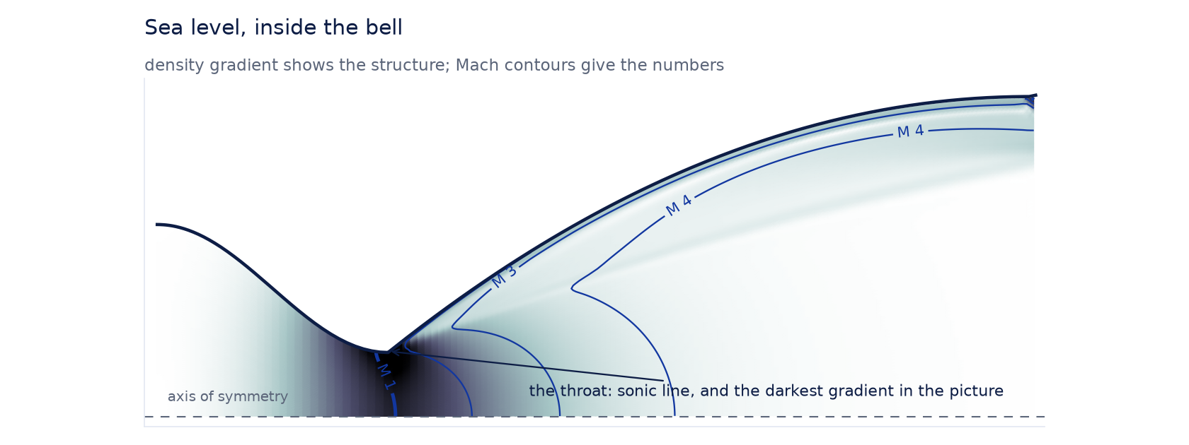
Gas accelerates through a narrowing passage. At the narrowest point — the throat — it can reach the speed of sound, and once it does, something abrupt happens to the information flowing through the engine. Pressure signals travel at the speed of sound. If the gas at the throat is already moving outward at exactly that speed, a pressure disturbance downstream can never work its way back upstream past it. The throat becomes a one-way valve for information.
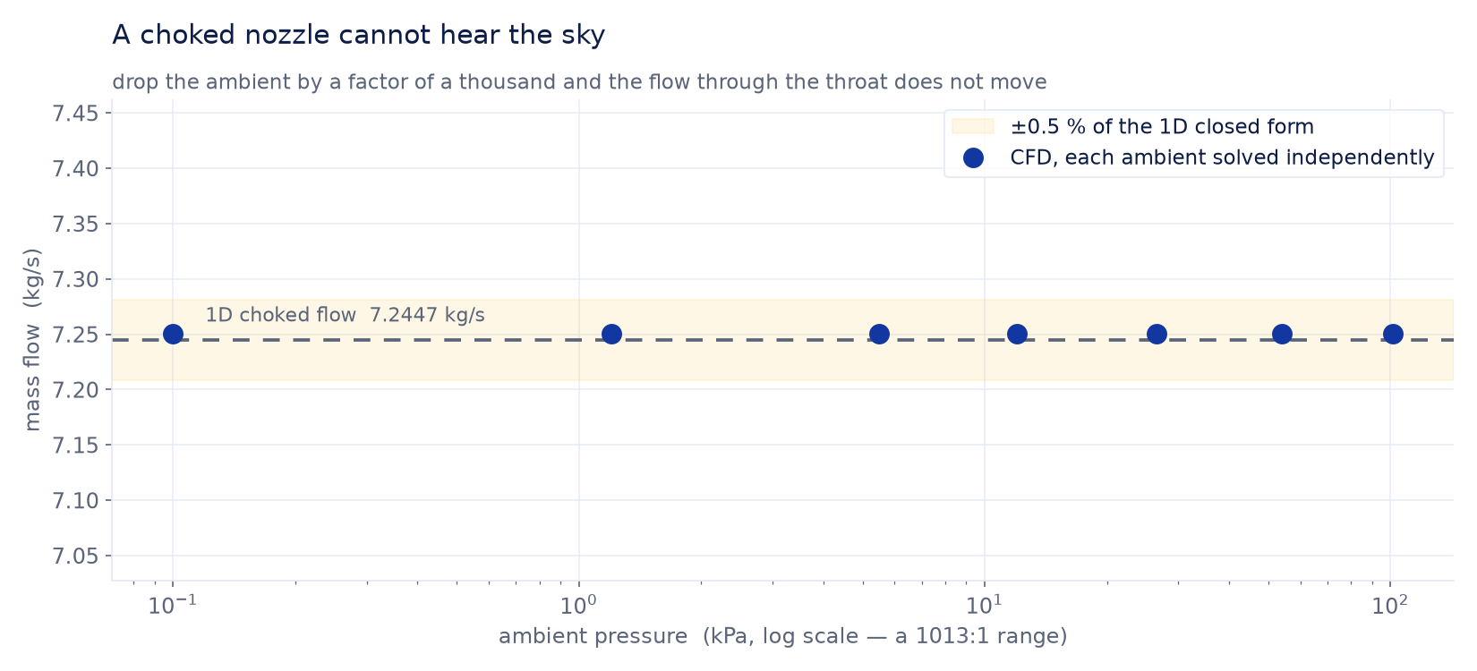
That is choking, and its consequence is severe: the chamber has no way of knowing what the outside world is doing. The mass flow is fixed entirely by conditions upstream of the throat — chamber pressure, chamber temperature, throat area — and the ambient pressure has no vote.
This is a strong claim and a testable one, so we solved the same nozzle seven times, once at each of seven ambient pressures spanning sea level down to near-vacuum, and compared the mass flow.
So where does the extra thrust come from?
Thrust has two parts. The first is momentum: mass flow multiplied by the speed the exhaust leaves at. We have just established that both are fixed, so that term is a constant. The second part is a pressure term — the exhaust leaves the nozzle at some pressure, the atmosphere pushes back on the exit area at its own pressure, and the engine collects the difference multiplied by the exit area.
At sea level the exhaust exits at roughly 15 kPa into 101 kPa of air. The atmosphere is pushing back harder than the exhaust is pushing out, and that term is a penalty of about four kilonewtons. Climb until there is nothing left to push back and the penalty becomes a bonus. Nothing about the engine changed; the term simply stopped being negative.
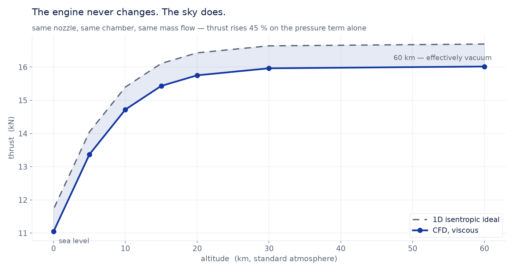
This is why engines come in sea-level and vacuum variants of the same design. You cannot change the momentum term without redesigning the machine, but you can choose the exit area, and that choice is a bet on which altitude the engine will spend its working life at.
The bell is smaller than the drawing says
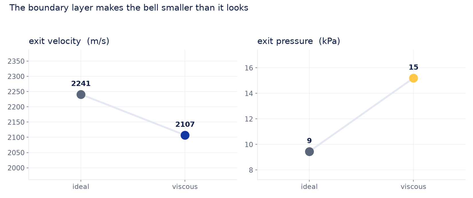
The ideal calculation and the viscous simulation agree on the mechanism but not on the numbers, and the disagreement is the most useful thing here.
One-dimensional theory predicts the exhaust leaves at 2241 m/s and 9.45 kPa. The simulation says 2110 m/s and about 15 kPa — six percent slower, and at appreciably higher pressure than the geometry promises. The cause is the boundary layer. Gas touching the wall is stationary, and the slow layer above it occupies room that the ideal calculation assumes is available for flow. The effective area ratio is smaller than the drawn one, so the gas does not expand as far, does not accelerate as much, and arrives at the exit still holding pressure it was supposed to have converted into speed.
And the diamonds, once the sky is thin enough
A plume only shows the bright repeating nodes people call shock diamonds when the exhaust leaves at roughly the pressure it is expanding into. This nozzle exits at Mach 5 and about 15 kPa, so at sea level it is severely over-expanded — the exhaust is at a seventh of the outside pressure, and the atmosphere crushes the supersonic core down to a single violent normal shock — a Mach disk — within centimeters of the exit. The normal-shock tables say what that costs: at Mach 5 the shock multiplies static pressure twenty-nine-fold and leaves the core at Mach 0.41 — subsonic, as the flow behind a normal shock always is. One shock, no train.
Climb to where the ambient is near the exit pressure and the picture changes completely. The mismatch becomes gentle, the exhaust turns through a weak oblique shock instead of a strong normal one, and the correction repeats: the shocks cross on the axis, reflect, cross again, and ring their way downstream. That repeating cell structure is the diamond pattern.
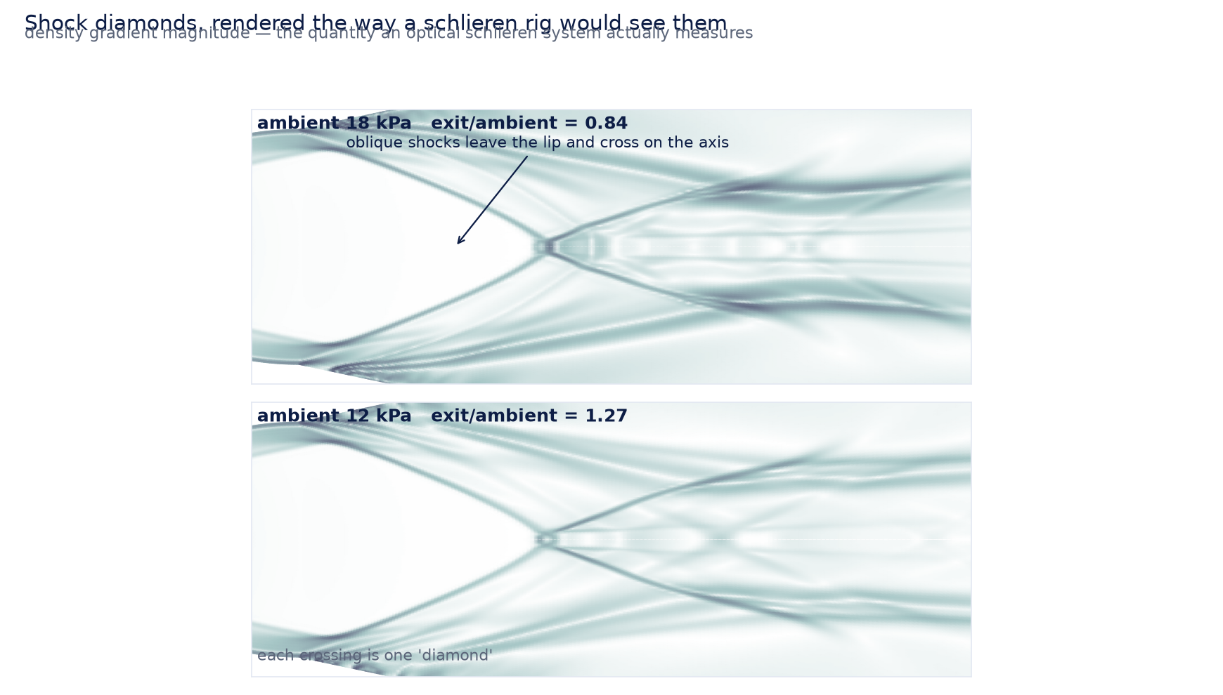
The mass flow, of course, does not care about any of this. It is 7.30 kg/s in every plume solution here, the same choked value the nozzle produced on its own. The diamonds are the exhaust negotiating with the atmosphere after it has left; the engine upstream is still deaf to all of it.
Making the answer trustworthy
A converged simulation that produces a plausible number is not the same as a correct one, so this model was made to prove four things before any figure above was quoted.
Mass has to be conserved: what enters the chamber must leave through the exit. It balances to 0.0014 %. The mass flow itself must match the closed-form choked relation computed independently at the model's own chamber conditions and throat area, which it does to 0.076 %. Thrust is computed two entirely separate ways — once by integrating pressure over the nozzle wall, which is where thrust is physically transmitted to the vehicle, and once from the momentum flux difference between the inlet and exit planes. Those two routes share a control volume but no data, and they agree to 0.3 % at every altitude.
The fourth check is the one that governs how many digits any of this deserves. Every result was recomputed on a mesh refined by half again in both directions, 60,750 cells against 27,000. Mass flow moved 0.6 %, exit velocity 0.3 %, exit pressure 3 %, and the headline thrust rise moved from 45.0 % to 45.2 %. So the thrust conclusion is solid, the velocity is good to three digits, and the exit pressure has earned two — which is why it appears above as "about 15 kPa" and not as 15,201 Pa.
What a model like this is for
The interesting engineering question about a nozzle is rarely whether it works. It is whether the exit area is the right bet, and that question is decided by the pressure term — the one that depends on the atmosphere the engine will actually fly through, not on the flow inside it. A model that pins the mass flow to a closed form, then shows the thrust curve bending purely through the pressure-area term, tells you what changing the bell would buy and what it would cost.
It also gives an honest correction to the textbook sizing. The ideal relations are excellent for setting a first geometry and are systematically optimistic about exit conditions, because they cannot know about the boundary layer. Six percent on exit velocity and a substantial miss on exit pressure is the difference between a nozzle that is correctly matched at its design altitude and one that is over-expanded and does not know it.
Part 2 — now fly it: the same nozzle from sea level to space
A nozzle that cannot hear the sky still has to fly through all of it. Keep the hardware fixed and sweep the sky instead — 32 flight conditions from pad to vacuum — and the one-condition story above becomes a regime map: over-expanded to under-expanded, shock diamonds appearing and fading, thrust climbing as the air thins. Here is that study in full.
This is a companion to our rocket-nozzle study. That one solved a single converging-diverging bell in detail. Here we took the same nozzle and let a script fly it — 20 altitude conditions for the internal flow and thrust, plus 12 more on an extended plume mesh for the shock diamonds, 32 Fluent solves in all, kicked off and swept unattended. The nozzle never changes; only the sky around it does.
One nozzle cannot win at every altitude
A rocket flies through a thousandfold drop in air pressure between the pad and space, but its nozzle is a fixed piece of metal. It is sized to expand the exhaust to one particular back pressure — one altitude. Everywhere else it is either over-expanded (the outside air is higher pressure than the jet, and squeezes it) or under-expanded (the jet is still higher pressure, and keeps spreading after it leaves). The design point is where they match.
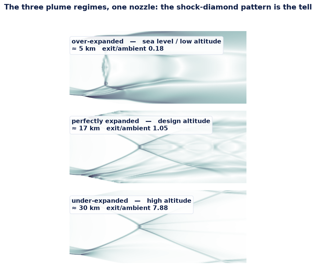
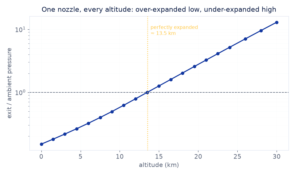
Inside the bell the two regimes look completely different. Over-expanded at sea level, the outside air pushes back hard enough to drive a shock up into the nozzle, and the flow can peel off the wall before it reaches the lip — separation that costs thrust and shakes the structure, and the reason engines are rarely run far over-expanded on the pad. Under-expanded up high, the flow fills the bell cleanly and does its remaining expanding outside, in the plume, where it costs nothing structurally but shows up as the spreading diamonds. The single design altitude is the tightrope strung between those two failure modes.
Watching the diamonds come and go
The shock diamonds in the hero are the exhaust re-pressurizing itself in a repeating train of shocks and expansions. They are most structured near the design point; at sea level the nozzle is so over-expanded that the supersonic core collapses through one strong disk instead of a tidy train, and very high up the cells stretch long and faint. You can read them quantitatively too, not just by eye.
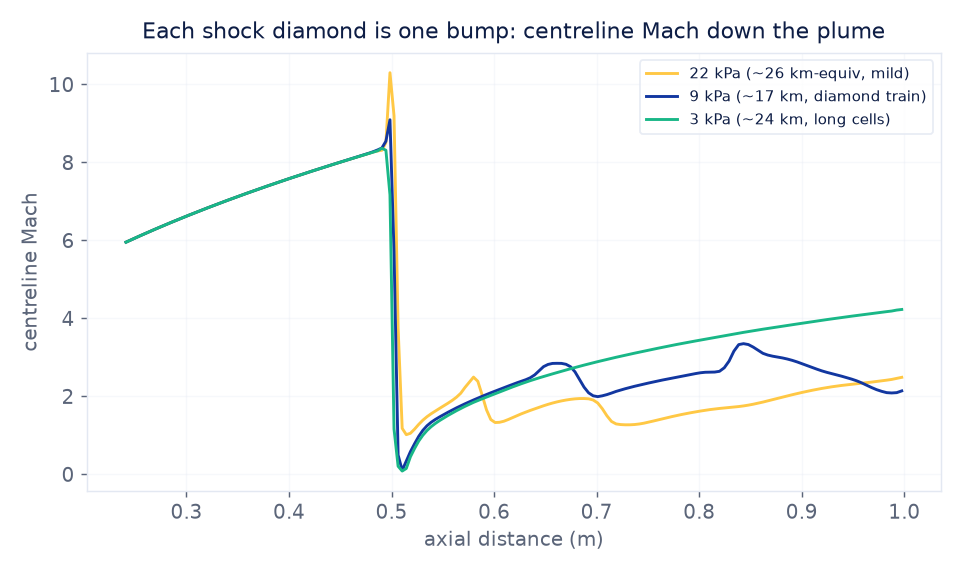
The mechanism is a feedback the plume cannot escape. Where the jet leaves under-expanded it fans out and over-accelerates; that over-expansion has to be turned back by a shock, which over-compresses the flow; the over-compression drives another expansion, and the cycle repeats, each round a little weaker, until turbulent mixing finally smears it away. One full expansion-and-shock cycle is one diamond. Their spacing is set by how far out of balance the jet was when it left the lip — which is why the pattern is a direct, visible readout of the altitude mismatch: tight and bright when the engine is only a little off its design point, long and faint when it is far from it.
What the automation did
The point of this study is as much the how as the physics. One nozzle case was piloted to fix the solver settings and the per-case cost, and then a script marched the ambient pressure through the whole flight envelope — anchoring at a well-behaved near-design point, continuing down toward vacuum, then reloading and climbing back up to sea level, each case warm-started from the last so the hard, separated, over-expanded points converge from a solution that is already close. 32 converged Fluent solves, their fields saved and post-processed into the map, the thrust curve and the animation, with no one at the keyboard. Scaling a validated single case into a swept envelope is the everyday value of scripting a solver, and it is exactly what turns one answer into a design map.
Thrust climbs as the air thins
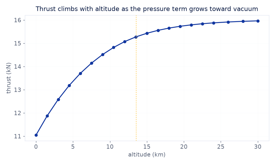
That constant mass flow is also the study's own conservation check: a choked nozzle's throat sets the flow regardless of what happens downstream, and the solver returns the same 7.25 kg/s at every one of the 20 conditions, matching the one-dimensional value to a fraction of a percent.
Why real rockets fight this
This is not an academic curiosity — it is why first stages and upper stages carry different nozzles, why a sea-level engine has a stubby bell and a vacuum engine an enormous one, and why exotic ideas like the aerospike and the dual-bell nozzle exist at all: each is an attempt to stay well-matched over more than one altitude, to claw back the thrust this sweep shows a fixed bell leaving on the table between the pad and space. The map here is the baseline those altitude-compensating designs are measured against.
It is also why the sweep, not the single case, is the deliverable. A booster spends only seconds near its design altitude and the rest of the climb off it, so the area under this thrust curve — not the design-point number — is closer to what actually reaches orbit. One converged solution tells you the engine works where it was sized; the swept envelope tells you what it is worth everywhere else, which is where it does most of its flying. Turning the first into the second is a scripting job on a solver that already had the physics right, and that is the entire point of running it this way.
Sizing a nozzle, a valve, or any passage where the flow chokes and the downstream world stops mattering? The same Ansys workflow behind this engine — Fluent solving the compressible field, mass flow pinned against the closed-form choked relation, thrust integrated two independent ways that had to agree, and a grid refinement deciding how many digits survived — is how Rand Simulation helps propulsion and flow-control teams find out what their geometry is actually worth before it is cut. That's innovation through insight.