Sixteen Waveguides Cross at One Point, and the Light Barely Notices
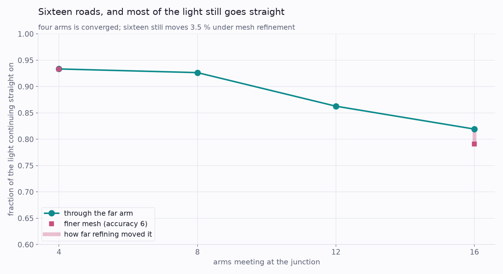
Somebody asked us whether light can get stuck in a traffic jam. Build an intersection where sixteen optical waveguides meet at a single point, send a beam in, and see what comes out the other side. The question sounds whimsical and the answer is genuinely surprising: about 80 % of the light goes straight through — a figure still drifting slowly downward on mesh refinement, so read it as “roughly four-fifths,” not a datasheet value — even with fifteen other roads joining at the same spot. Photons do not queue. But the intersection is not free either, and what it does cost has nothing to do with beams getting in each other's way.
Why light cannot jam, and why that is not the end of the story
Cars jam because they cannot occupy the same place at once. Light has no such rule. Maxwell's equations in ordinary glass and silicon are linear, which means two beams crossing the same point simply add: each one carries on exactly as though the other were not there. No momentum is exchanged, nothing is deflected, and the two beams leave with precisely the energy they arrived with.
That is a strong claim, so it is worth measuring rather than asserting. We drove one arm alone, then a second arm alone, then both together, and compared the field of the both-on case against the sum of the two single-arm cases — every point on the grid, every vector component.
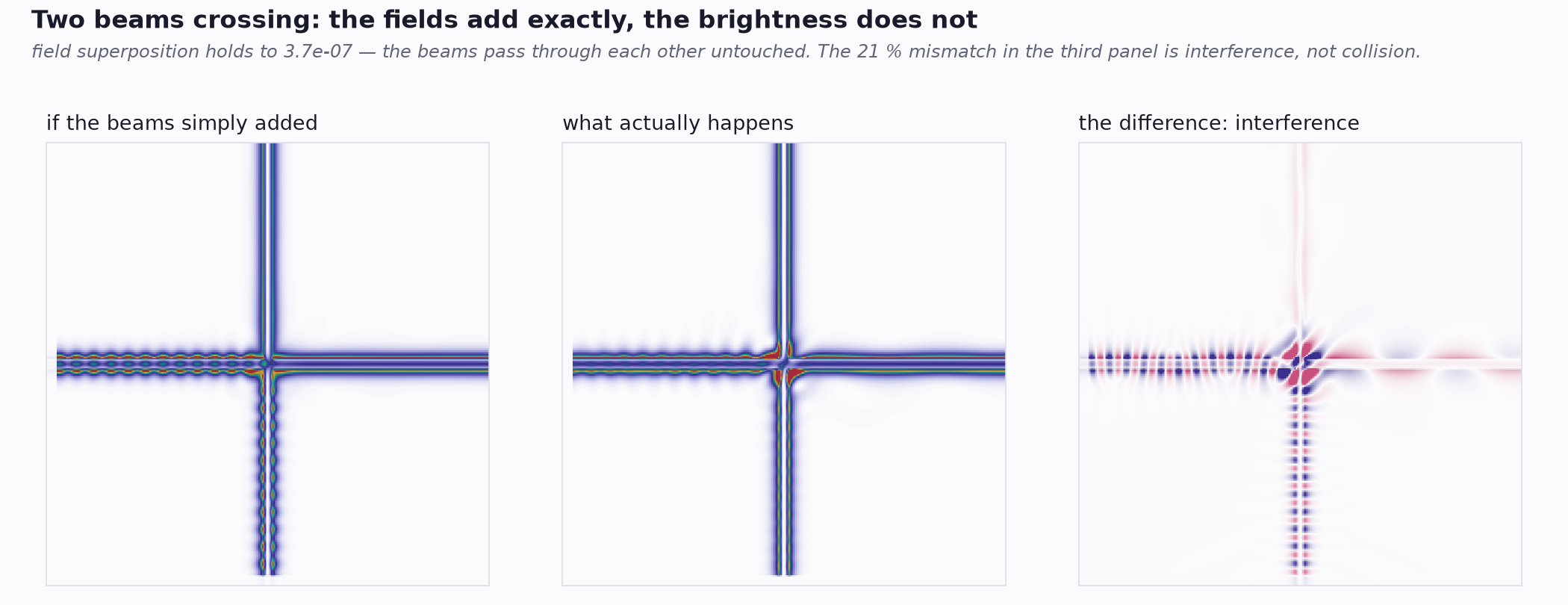
The distinction matters because it is the one people get wrong. Fields add; intensities do not. You can build a dark fringe where two bright beams overlap without a single photon being destroyed — the energy is simply somewhere else in the pattern. Nothing in that exchange slows either beam down or costs the junction anything.
So what does the intersection actually cost?
The model is a two-dimensional silicon slab guide in oxide (nSi = 3.4757, nSiO₂ = 1.444) at the telecom wavelength of 1550 nm, with N arms meeting at the origin and a mode launched down one of them. The guide's one confining dimension — its in-plane width in this 2D world — is set to 220 nm so the slab is single-mode (the check is in the scope box). A note for SOI readers so the number does not mislead: on a real chip, 220 nm is the canonical thickness of the silicon layer, and single-mode ridge widths at 1550 nm run about 450–500 nm; our 220 nm plays the role of the confining dimension in a model that has only one. A single 90-degree crossing — the everyday case in any photonic circuit where two signal paths must pass — costs remarkably little.
The reason is that a junction stops being a junction
Waveguides have width. Arms of width w meeting at a point must overlap each other within a radius of roughly wN/2π, so the center of the intersection is not a crossing at all — it is a solid blob of silicon with waveguides attached. That blob grows as roads are added: 0.28 µm across at four arms, 1.12 µm at sixteen.
Inside the blob there is no lateral confinement, because there are no longer any edges to confine against. The mode is briefly a free beam, and free beams diffract. The relevant yardstick is the Rayleigh range — the distance a beam travels before it spreads appreciably — which for this mode is only about 0.085 µm. At sixteen arms the light crosses roughly thirteen Rayleigh ranges completely unguided before the far arm catches it again.
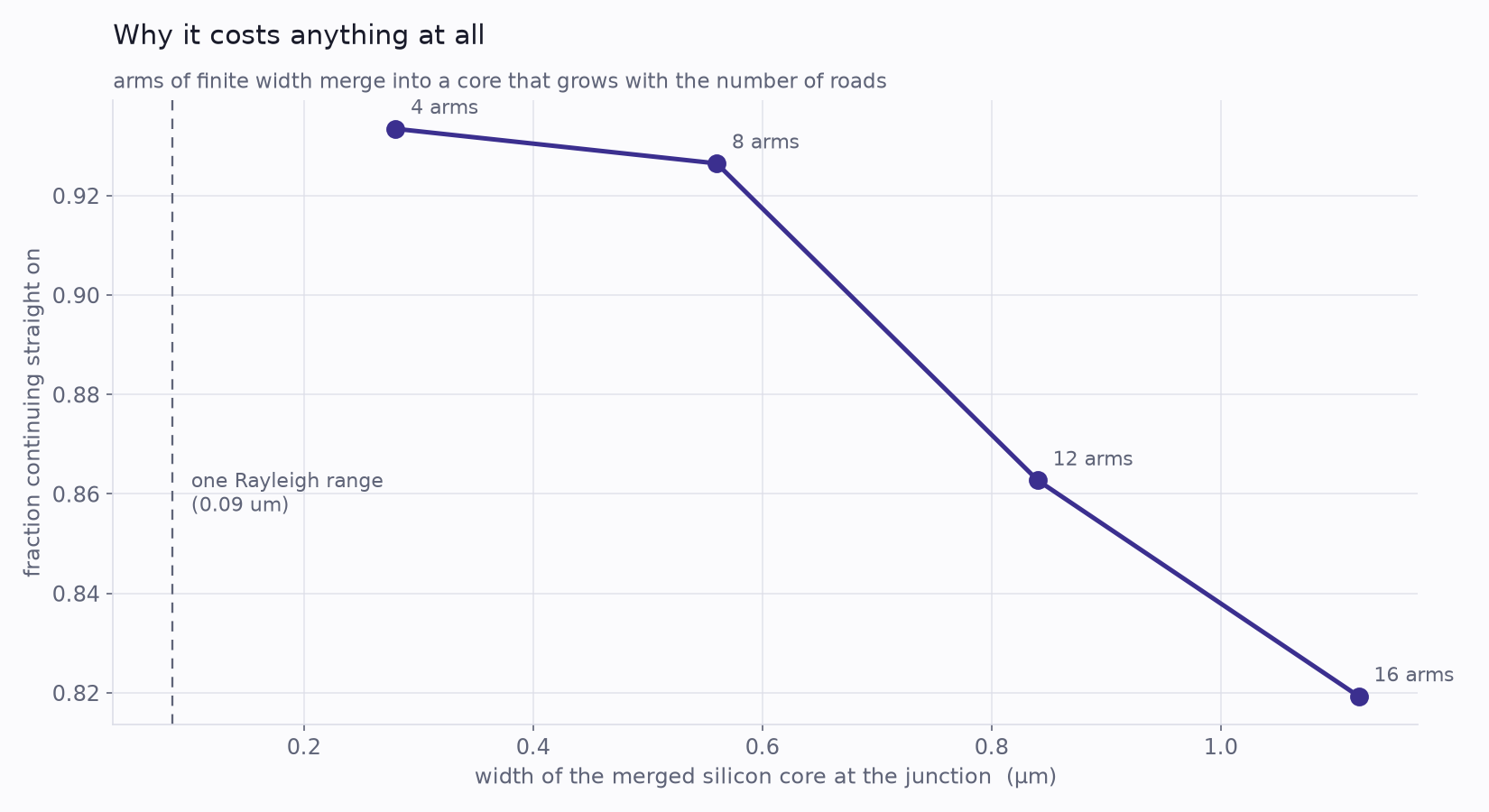
This also explains something counter-intuitive. A narrower guide makes a smaller merged core, so it survives a crowded junction better — even though a narrower guide holds its light more loosely everywhere else. The junction rewards the opposite of what the straight sections do.
Making the answer trustworthy
A simulation that produces a plausible number is not the same as a simulation that is right, so this one is asked to prove three things before any result is quoted.
The first is that energy is conserved. Four monitors form a closed box around the junction, and the net power crossing that box must be zero — power in equals power out for a lossless material. It comes to 0.006 of the injected light, which is zero to within the measurement. The second is symmetry: the two side arms of a four-way crossing are geometrically identical, so they must receive identical crosstalk. They agree to 0.00 %. Any asymmetry there would be setup error, and it would bound how many digits of everything else were real.
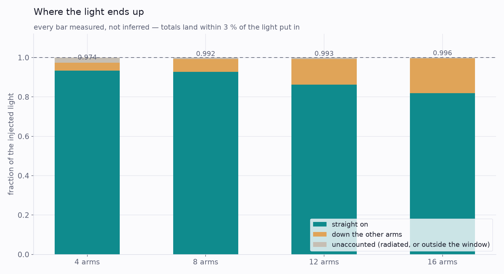
The third is convergence, and it is the one that changed what this article is allowed to say. Every number here was first computed on a working mesh. Re-solving on a finer one moved the four-arm result by 0.01 % — settled — but moved the sixteen-arm result by 3.5 %, from 0.819 to 0.791. That is not a converged answer. It is quoted here as "about 80 %" for exactly that reason, and the direction is instructive: a coarse grid smooths away the small features at a tight sixteen-arm pitch, so refining finds more loss rather than less.
What to take from it
The community question was whether light jams, and the honest answer has two halves. It does not: beams pass through one another to within four parts in ten million, and no amount of traffic changes that. But an intersection is a physical object, not a mathematical point, and the object costs something — a fraction of a decibel for an ordinary crossing, rising gently as you crowd more roads into the same spot.
For anyone laying out a photonic circuit, that is a useful pair of facts. Routing signal paths across one another is cheap and you should not contort a layout to avoid it. What deserves attention is not the number of crossings but their geometry: the width of the guides where they meet, and how much undifferentiated material ends up at the junction. Those are the knobs, and a model like this is how you find out which way to turn them before committing to a mask.
Have a photonic layout where signal paths have to cross — and you need to know what each junction actually costs before it is committed to a mask? The same Ansys workflow behind this crossing — Lumerical FDTD resolving the fields directly, power per arm integrated from the Poynting vector where mode expansion cannot reach, checked against analytic slab modes and a closed-box energy balance, with a mesh study deciding how many digits survive — is how Rand Simulation helps photonics teams price a junction before the geometry is frozen. That's innovation through insight.