Designing a Better Crumple Zone
This is a companion to our crush-tube study. That one crushed a single thin-walled tube and validated the physics against the textbook mean-crush-force formula. Here we kept the same solver and the same validated tube and changed only one thing: who chooses the next design. A script and an optimizer did, 36 times over, unattended.
A crumple zone has two jobs that fight
The rails and crush cans in a car’s front end have to do two things that pull in opposite directions. They must absorb energy — turn the car’s motion into crushed metal so it doesn’t reach the people — and they must do it without spiking the force, because peak force is what the occupants feel as deceleration. A tube that is too stiff absorbs plenty but hits like a wall; a tube that is too soft is gentle but bottoms out before it has soaked up the crash. The good designs live on a curve between those extremes, and finding that curve is the job.
Here the “crash” is a fixed one: a 275 kg mass at 15 m/s, about 31 kJ of kinetic energy, dropped onto a AA6060-T4 tube fixed at its base. Every design in the sweep has to swallow the same energy; what changes is the force it charges to do it, and the mass of metal it needs.
Letting the search drive
The workflow is the point. One tube was piloted first to fix the solver settings and the per-case cost — the folding contact, the mass scaling, the run time — and to check the mean crush force against the closed-form value from the base study (about 21.1 kN; the model lands within roughly 20 % of it, the expected direction for a dynamic, untriggered crush). Then optiSLang 26.1.0 took over. It laid down a space-filling set of 28 designs across wall thickness, taper and bead depth, LS-DYNA crushed every one, and the responses came back to fit a metamodel — a fast surrogate that stands in for the solver so the optimizer can explore thousands of designs it never has to run.
The honest part is the last step. A metamodel’s prediction does not count until a real solve confirms it, so the search took its predicted best trade-offs and crushed them for real in LS-DYNA — 36 converged solves in all, 36 of them clean. That is the difference between a search and a guess: the front you see was drawn by the surrogate but every corner of it was checked against the actual solver.
Why not simply grid it? A full factorial over three variables, even at a coarse five levels each, is well over a hundred solves — and most of them land in regions no sensible design would occupy, thick walls with deep triggers that are both heavy and weak. The space-filling sample spends its solves spread across the whole box, the metamodel covers the gaps between them for free, and the confirmations are aimed only at the front that actually matters. That is the same reasoning optiSLang applies at industrial scale, where one solve can be an hour of cluster time and a brute-force grid is simply not affordable. Here it is the difference between a few dozen crushes and several hundred for the same map.
What the search found
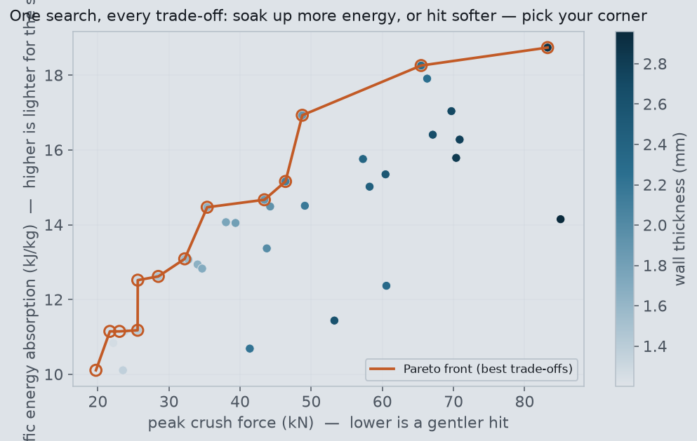
The colors tell the first story on their own: peak force is almost entirely a wall-thickness effect. Thin-walled tubes sit on the left (gentle) and thick ones on the right (hard), in a clean gradient, because a thicker wall simply takes more force to fold. There is no free lunch hiding in taper or bead depth that lets a thick wall hit soft.
The trigger bead earns its keep
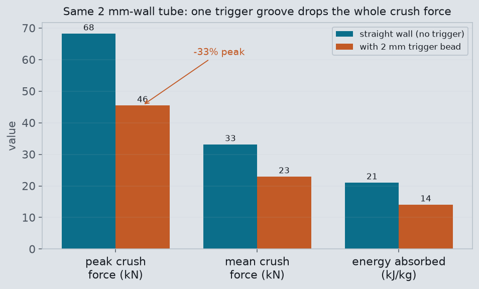
This is the knob that buys a designer something wall thickness cannot. Wall thickness moves you along the trade-off — harder and heavier, or softer and lighter. Adding a trigger groove to a fixed wall instead drops the whole crush force at once. One honest surprise from the model: the ratio of peak to mean force barely moved — in this dynamic crush the groove lowers the entire force level rather than just shaving the opening spike the way the quasi-static rule of thumb suggests. That softer crush is paid for in energy absorbed, and across the search the bead is the second-largest lever on absorption after wall thickness — the one variable that lets a thin, light tube reach the gentle corner of the front at all.
Reading the metamodel honestly
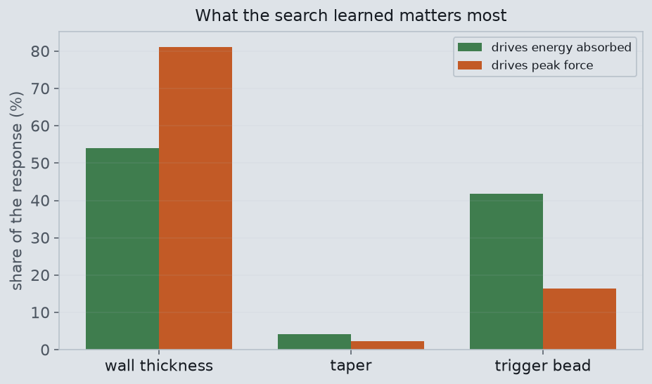
The surrogate itself reports how much to trust it. Peak force was highly predictable — its metamodel scored a coefficient of prognosis of 0.96 on held-out designs, meaning a simple surface captures it almost perfectly, which fits a quantity dominated by one variable. Energy absorption was harder, at 0.59: folding is a nonlinear, contact-driven process, and a smooth surface only partly captures it. That gap is worth stating plainly rather than hiding — it is why the front’s corners were confirmed with real solves, not read off the surrogate. The taper result is the quiet win: the search spent solves learning that a variable a designer might agonize over does almost nothing here, which is exactly the kind of thing a sweep tells you and a single case never can.
Part 2 — where this started: How a Crumple Zone Absorbs a Crash
The design search above stands on a first study that asked the simpler question: what actually happens, fold by fold, when one crush tube takes a crash? That original study follows in full.
The most important part of your car is the part that's designed to be destroyed. In a crash, the front end of a modern vehicle isn't supposed to stay strong — it's supposed to fold up like an accordion, trading its own structure for your life. We pointed LS-DYNA at the single component that does most of that work: a thin-wall steel tube, hit head-on at 10 m/s, and watched it eat 8 kilojoules of kinetic energy one fold at a time.
The physics: turning speed into folds
A crash is, at heart, a problem of getting rid of kinetic energy in a hurry. A 200 kg striker moving at 10 m/s carries 10 kJ. Stop it instantly against something rigid and that energy spikes back as a brutal deceleration — the kind that hurts people. The trick a crumple zone plays is to spend that energy slowly, over distance, by bending metal.
When you axially crush a thin-wall tube, it doesn't just squash uniformly. It buckles into a repeating train of folds — the classic accordion. Each fold is a set of plastic hinges where the steel yields and wraps over on itself, and every hinge soaks up a fixed quantum of energy. String enough folds together and you get something beautiful: a roughly constant resisting force over a long stroke. Constant force over distance is the textbook definition of an ideal energy absorber, and it's exactly why automakers build the front rails of a car to fold this way on purpose.
A good crumple zone isn't strong. It's predictably, controllably weak — and that's the whole point.
Inside the model
Geometry and mesh
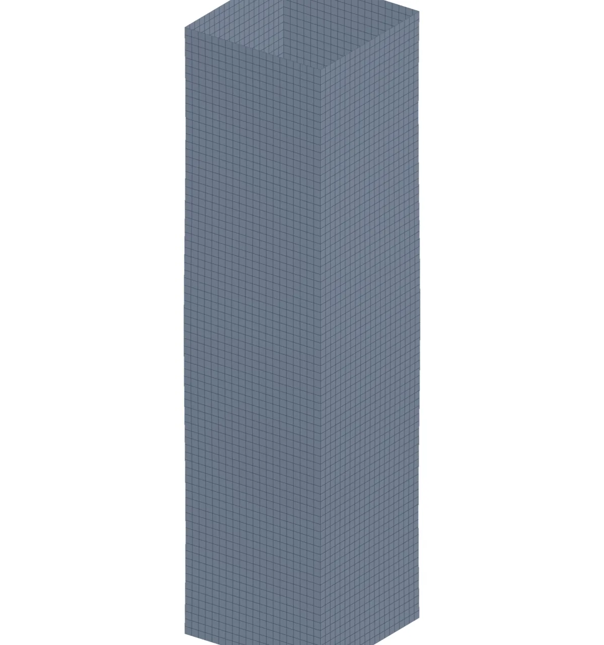
The part is deliberately humble: a 60×60 mm square tube, 1.5 mm wall, 240 mm long — a stand-in for the kind of crush rail or bumper-beam crush can you'd find behind a fascia. We meshed it with roughly 3 mm Belytschko–Tsay shell elements, 6,400 of them, fine enough to resolve the individual folds and the global force history without drowning the explicit time step. Thin-wall folding is a shell problem through and through, so there are no solids here — fidelity where it matters, not where it doesn't.
Material, loads and solver
The tube is mild steel modeled with *MAT_PLASTIC_KINEMATIC: yield 300 MPa, tangent modulus 763 MPa,
and — crucially — Cowper–Symonds strain-rate hardening with C = 40 s⁻¹ and p = 5. That rate term matters: steel hit
fast is meaningfully stronger than steel pushed slowly, and leaving it out would underpredict the crush force.
The "car" is idealized as a 0.20 t *RIGIDWALL_PLANAR_MOVING launched at 10 m/s, and self-contact during
folding is handled by *CONTACT_AUTOMATIC_SINGLE_SURFACE so the tube walls don't pass through each other as
they wrap up. The whole event runs in 15 ms of explicit LS-DYNA time.
A key decision worth calling out: the deck went through three iterations before it ran clean. LS-DYNA's
comma-format multi-card keywords demand exact card counts — get the card count wrong and the deck reads as the wrong
keyword blocks (we collected 29 errors that way). The fix was to lean on single-card-friendly keywords like
MAT_PLASTIC_KINEMATIC and the moving planar rigid wall, which keep the deck simple and
readable.
The result
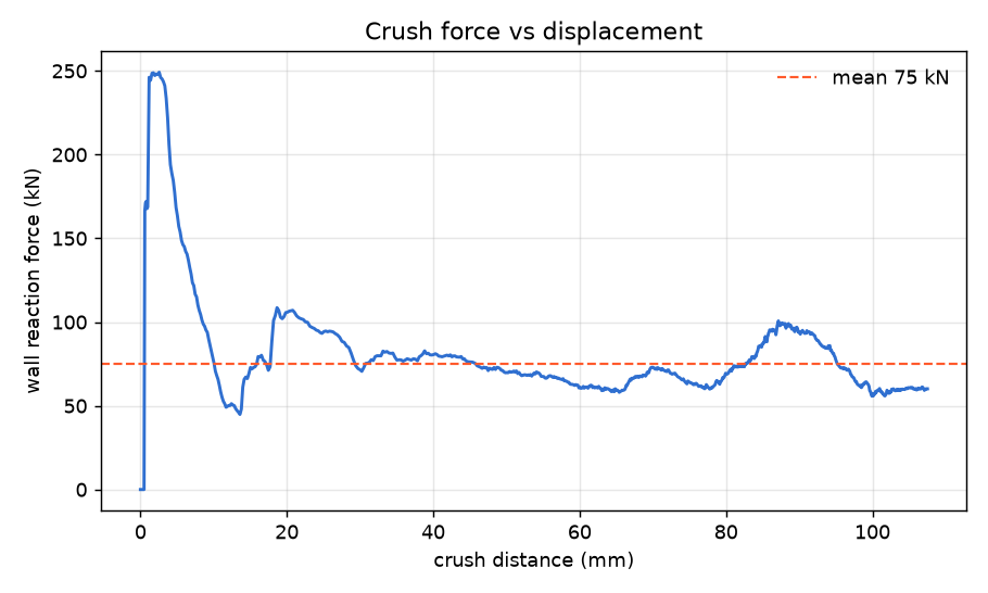
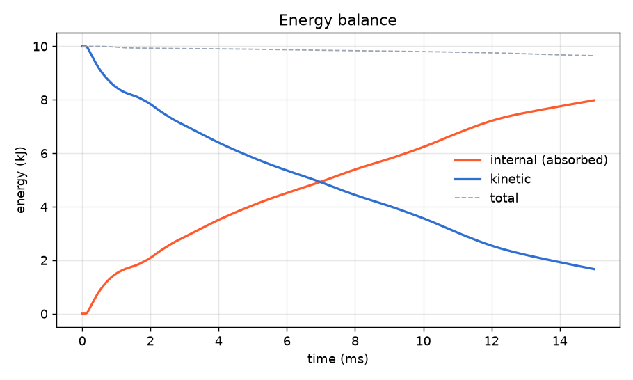
Is it right?
Three independent checks back up the number — and the most interesting one is deliberately not a one-to-one match.
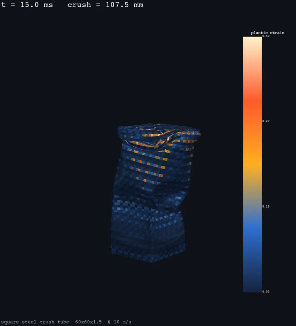
The classic Abramowicz & Wierzbicki (1984) theory for a square box column gives a quasi-static mean crush force of roughly 35 kN for these dimensions. Our model predicts 74.2 kN — about 2.1× higher. That gap is the physics working as intended: at a 10 m/s collapse, the steel is straining fast enough that Cowper–Symonds rate hardening boosts the dynamic flow stress by roughly 2.2× (with inertial folding effects adding a little more on top). In other words, the FEA force is consistent with the static benchmark once you scale it by the rate enhancement — it is supposed to be larger, not equal.
The other two checks are housekeeping that earns trust in the number: total energy was conserved to 99.7%, so the 8 kJ of absorbed energy is real and not numerical drift; and hourglass energy stayed at 0.36% of internal energy — far below the 10% rule of thumb — so the reduced-integration shells aren't faking stiffness.
The real-world connection
This little tube is a microcosm of why surviving a head-on crash today is a completely different proposition than it was sixty years ago. The most visceral demonstration of that progress is the IIHS 50th-anniversary test, where a 1959 Chevrolet Bel Air — a slab of heavy, "solid" Detroit steel with essentially no managed crush structure — was run head-on into a 2009 Chevrolet Malibu. The old car, the heavier one, the one people remember as "built like a tank," is the one that loses. Its passenger compartment collapses; the modern car's crumple zone folds up out front exactly like our tube and keeps the cabin intact.
Engineers call the intentional weak points that trigger that fold pattern "crush initiators," and the goal is always the same one we measured here: a stable plateau of force over the longest possible stroke. (For a friendly primer, HowStuffWorks has a good walkthrough, and the IIHS YouTube channel is full of slow-motion crumple footage.) Get the geometry, the material, and the rate behavior right in simulation, and you can tune that plateau long before you ever bend a real piece of steel.
Have a part whose job is a trade-off, not a single number? Crush structures, brackets, heat sinks, motors, antennas — the real question is usually “what is the lightest, cheapest version that still meets the limit,” and that is a front to be mapped, not a point to be solved. Pairing a validated Ansys solve with an optiSLang search turns a pile of solver runs into that map, and it is a few days of work. We do this across the Ansys structural, fluids and electromagnetics tools. Rand Simulation — innovation through insight.