Will a Propeller Cavitate? Reading the Answer Off the Pressure Field
Spin a propeller fast enough and the water on the low-pressure side of the blade does something startling: it boils — not from heat, but because the pressure drops below the vapor pressure of water at room temperature. Those vapor pockets collapse violently milliseconds later, pitting the blade like a jackhammer, roaring across a submarine’s sonar signature, and stealing thrust. It’s called cavitation, and the first question any propeller designer asks is: will this blade cavitate, and where? You can answer it from a single-phase CFD solve, before you ever model a bubble.
1 · A blade is a stack of wings
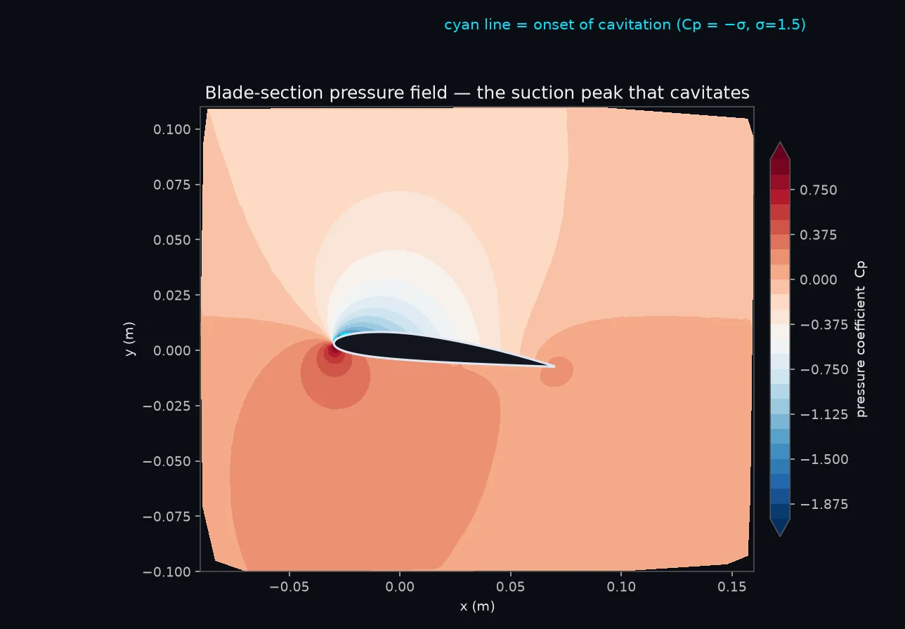
A propeller blade is a twisted stack of hydrofoil sections, each one a little wing generating lift (which, pointed forward, is thrust). So we model one representative section — a cambered NACA foil — in a water tunnel and solve the flow around it. At a 6° angle of attack and 15 m/s (typical of a fast outer-radius section) the section carries a healthy lift coefficient of 0.85 with a drag coefficient of 0.021: a well-behaved, efficient little wing. The interesting part is what the pressure does.
2 · The tell: an impossible pressure
On the suction side, near the leading edge, the flow accelerates to over 23 m/s and the static pressure plunges. The single-phase solve reports a minimum absolute pressure of about −122 kPa. That number is impossible: it is below a perfect vacuum. Water cannot sustain it. Long before the pressure could reach anything like that, the water reaches its vapor pressure (about 3.5 kPa at room temperature) and flashes to vapor — it cavitates. The unphysical negative pressure a single-phase model predicts is not an error to fix; it is the clearest possible warning that the real flow will cavitate, and hard.
3 · Putting a number on it: the cavitation number
Engineers turn that warning into a clean criterion. The cavitation number σ measures how much margin against boiling the surrounding water has — how far the ambient pressure sits above vapor pressure, scaled by the flow’s dynamic pressure. A propeller running deep and slow has a high σ (lots of margin); running shallow and fast, a low σ. Cavitation begins wherever the local suction, expressed as the pressure coefficient −Cp, exceeds σ.
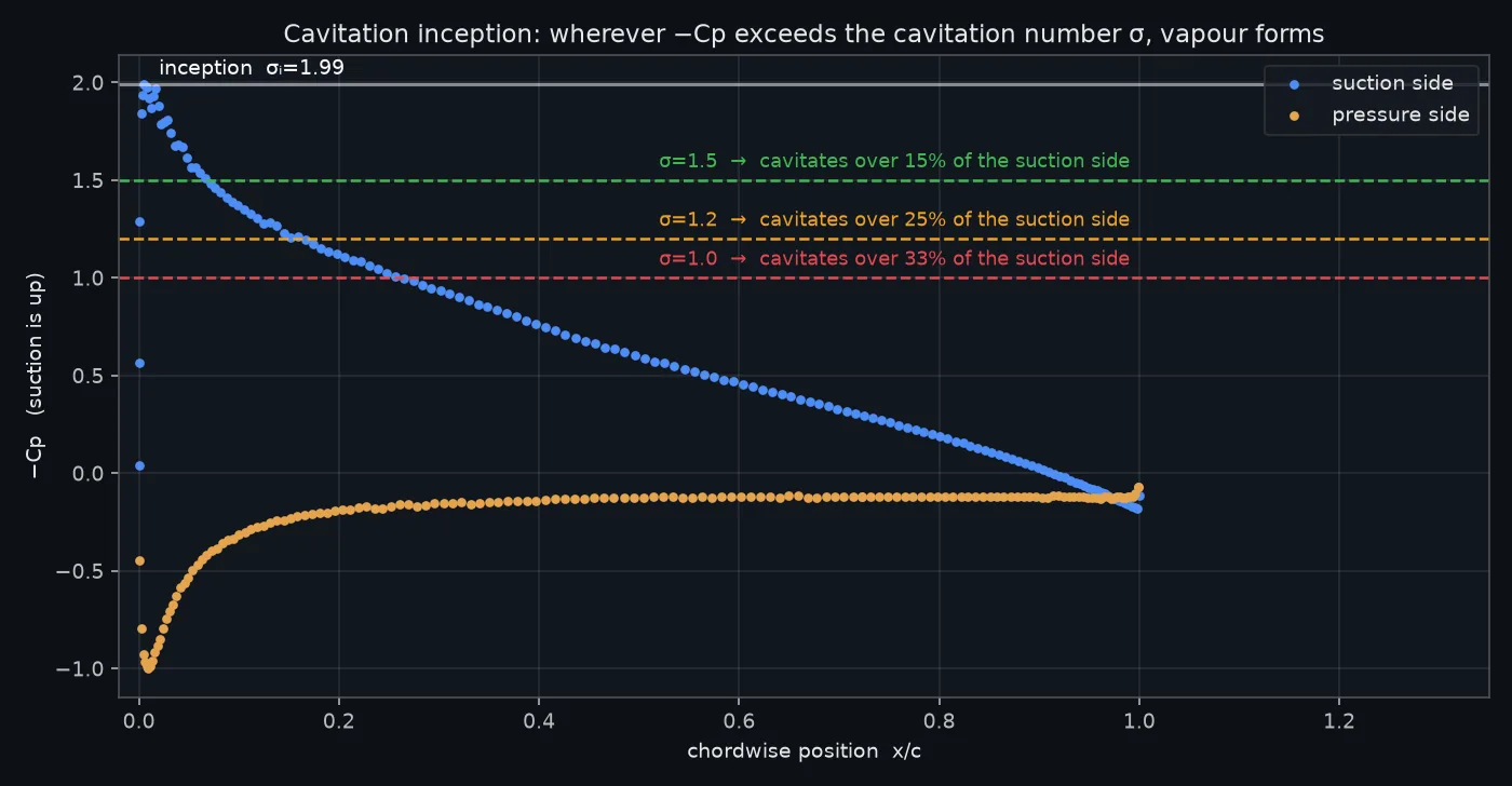
So this section’s answer is precise: it starts to cavitate the moment σ drops below 1.99, the cavity nucleates at the leading edge where the suction is sharpest, and it grows aft as conditions get more aggressive. That is exactly the information a designer needs — which sections cavitate, at what operating point, and over how much of the blade — and it comes from one steady solve.
4 · Why it matters on a real propeller
The outer sections of a propeller move fastest, so they see the lowest σ and cavitate first — which is why cavitation damage clusters near the blade tips, along with the tip-vortex cavitation that trails off them. The consequences are the whole reason marine propellers are so carefully shaped: collapsing vapor bubbles hammer the surface with microjets and erode the metal; the broadband roar of millions of collapses is a warship’s acoustic signature and a pump’s telltale rattle; and once a cavity sheet covers enough of the blade, lift breaks down and the propeller simply stops delivering thrust. Pushing inception to lower σ — more blade area, tuned section shapes, skew — is a central goal of propeller design, and the inception analysis above is how you check whether you’ve done it.
You don’t need to model a single bubble to know a propeller will cavitate. When the pressure field asks for a pressure that can’t exist, the water has already given you the answer.
Marine cavitation CFD in Ansys Fluent (2026 R1).
5 · Honest scope
- This is a cavitation-inception study: it predicts where and at what σ the blade begins to cavitate, and how far the vapor spreads, from the single-phase pressure field. It does not resolve the shape of the vapor cavity or the thrust-breakdown at very low σ.
- Resolving the actual vapor sheet needs a two-phase (mixture + Schnerr-Sauer) solve — scoped as the next step for this study (the cavitation source term is numerically stiff, a known property of this model class, and deserves its own careful setup). The inception result stands on its own and is the standard first screen in practice.
- A single 2D section, steady RANS with wall functions, and a representative foil — not the full 3D twisted blade, the unsteady tip vortex, or a calibrated section. The trend and the inception number are robust; absolute values are indicative.
Is there a propeller, impeller, or pump blade in your product that pits, rattles, or quietly loses thrust — and nobody can say at what operating point the trouble starts? One steady single-phase Ansys Fluent solve (RANS, SST turbulence) reading inception straight off the pressure field — σⁱ = 1.99 at the leading edge, vapor across a third of the chord by σ = 1.0, and the two-phase mixture + Schnerr-Sauer sheet solve honestly scoped as its own next step — is how simulation tells you where and when a blade will cavitate before a water-tunnel campaign or an eroded blade tells you the hard way. That's innovation through insight.