Why a Wireless Charger Is So Picky About Where the Phone Sits
Two Coils and One Number That Governs Everything
A wireless charger is a transformer with an air gap. A flat spiral “pancake” coil in the pad (the transmitter, Tx) drives an alternating magnetic field at the Qi operating frequency — we used 140 kHz; a matching coil in the phone (the receiver, Rx) picks up whatever fraction of that field links it and rectifies it to charge the battery. Unlike the iron-cored transformer in a wall adapter, the two coils are only loosely coupled by design, with nothing but air, plastic, and a few millimeters between them. The single number that governs the whole exchange is the coupling coefficient
k = M / √(Ltx·Lrx) (0 ≤ k ≤ 1),
where M is the mutual inductance between the coils and Ltx, Lrx are their self-inductances. There is no honest closed form for k of a real pancake coil with a ferrite shield at an arbitrary lateral offset — the textbook coaxial-loop formula only holds on the shared axis. So we let Maxwell compute the inductances directly from the solved magnetic field. We modeled a generic Qi-style pair — a 43 mm transmit coil and a 40 mm receive coil, ten litz turns each, each backed by a high-permeability MnZn ferrite tile that channels the flux, plus an aluminum plate standing in for the phone's metal back — and read a two-winding inductance matrix at each alignment.
Before trusting a single offset number, we checked the aligned case against physics we already know. The solved coupling at perfect alignment, k = 0.730, matches the classical coaxial-loop mutual-inductance formula's k = 0.733 to within 0.4% — even though the ferrite boosts the individual inductances about 2.1× above their air-core values. That is the strong physical check: ferrite lifts L and M together, so it barely moves k, and the solved coupling lands right on the closed form. Every solve converged to an energy error near 0.6% over twelve adaptive passes on roughly 40,000 tetrahedra.
How Fast It Falls Off
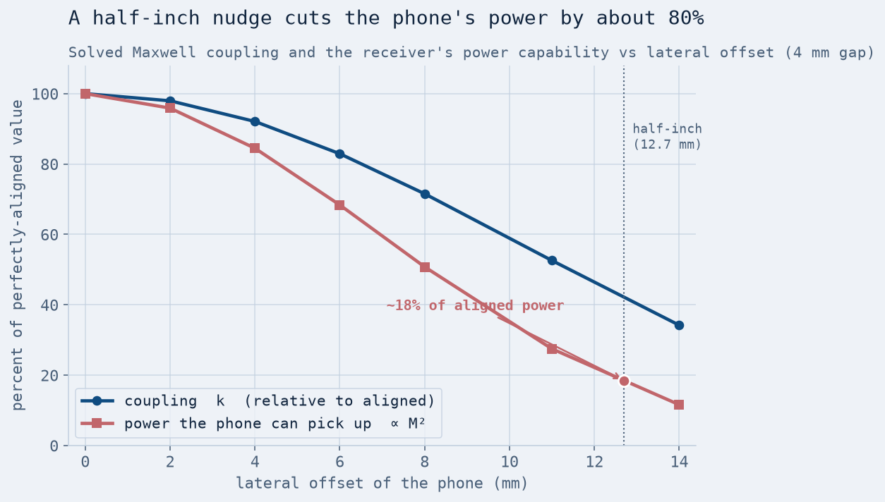
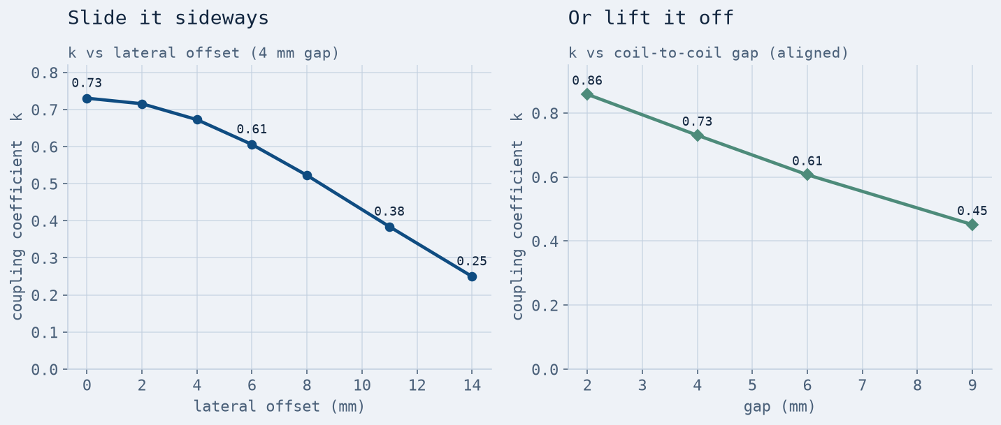
Here is the answer to the question the pad makes you ask every morning. Slide the phone sideways and the mutual inductance drops fast while the self-inductances barely change, so k falls steeply: 0.73 aligned, 0.67 at 4 mm, 0.52 at 8 mm, 0.38 at 11 mm, 0.25 at 14 mm. Coupling itself roughly halves at a half-inch offset. But k is not the thing you feel — delivered power is, and the power a loosely-coupled link can transfer scales with k2 (more precisely, with M2). Square the falloff and it turns brutal: the power the phone can pick up drops to 68% at 6 mm, 51% at 8 mm, and just 28% at 11 mm. Interpolated to a literal half-inch, 12.7 mm, the phone is down to about 18% of the power it had when centered — an 80% loss for half an inch of travel. That squared law is the mathematical reason a small nudge feels like an on/off switch.
Lifting the phone off the pad does the same thing along the other axis. Holding the coils centered and opening the gap, k runs 0.86 at 2 mm, 0.73 at our nominal 4 mm, 0.61 at 6 mm, and 0.45 at 9 mm — which is why a thick case or a coin stuck to the back of the phone matters, and why the coils want to be as close as the plastic allows.
The Twist: The Link Never Gets Inefficient
You would expect all that lost power to show up as a collapsing efficiency. It does not. Feeding the solved inductances and the eddy-current winding resistance into the standard series–series resonant-link relations, the coils' quality factor comes out around Q ≈ 71 (litz wire keeps the resistance low), and the best-case link efficiency stays high across the whole sweep: 96% aligned, still 89% at the worst 14 mm offset. What collapses is the link's figure of merit U = k2·Qtx·Qrx, which falls about nine-fold — and U is what sets how much power the link can actually move at a matched operating point, not how efficiently it moves the last bit.
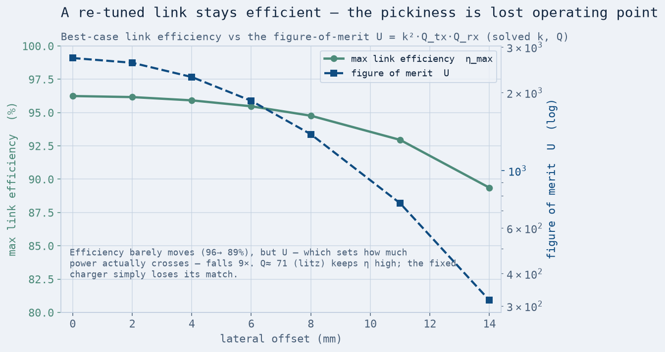
That is the honest resolution of the puzzle. Charging does not stop because the physics becomes lossy; it stops because a fixed charger, resonant-tuned and current-limited for a centered phone, falls off its operating point as the coupling drops. The received voltage sags, and the charger's control loop pushes more current to hold it — until it hits its limit and the receiver can no longer maintain the voltage its regulator needs. Then it gives up. We modeled the electromagnetic link, not that control loop, so we report the coupling and the power capability it sets, and name the loop as the thing that turns a steep curve into an abrupt cutoff.
Where the Wasted Power Goes — and Why It's Subtler Than It Sounds
The companion question was thermal: a badly-placed phone gets warm, so where does the heat land? We drove the transmit coil at a fixed, realistic current (1.4 A rms) and solved the eddy-current losses in the coils, ferrite, and aluminum shield, then fed those into an Icepak steady-state temperature solve. The result is a useful surprise, and it is worth stating plainly rather than forcing it to match the folklore. At a fixed drive current, the hardware barely warms differently when you misalign it. The peak temperature rise is 6.4 °C aligned and 6.0 °C at 11 mm — essentially flat, because most of the heat is the transmit coil's own resistive loss, which the geometry does not change. The aluminum shield's stray-current loss actually falls as the phone slides away, because less of the transmit field reaches it.
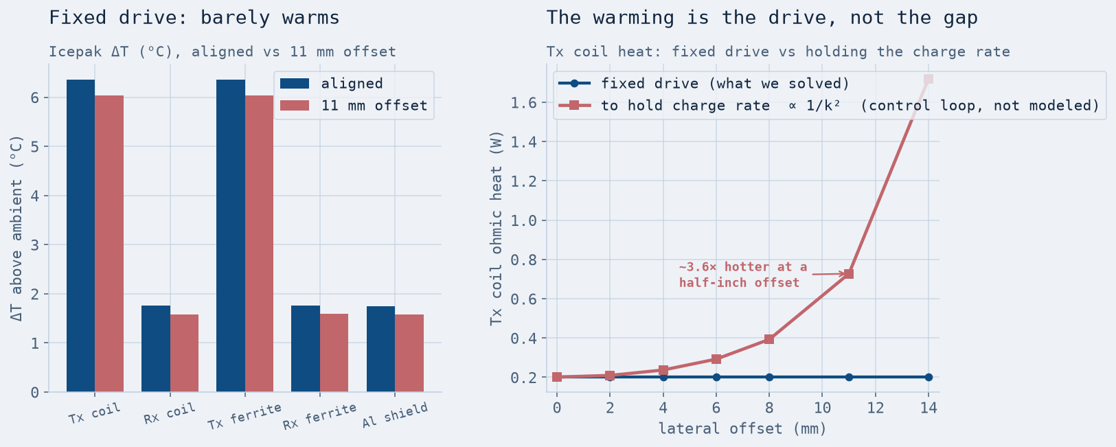
So why does a misaligned phone genuinely feel warm? Because a real charger does not hold the drive fixed — it cranks the current up to fight the falling coupling and keep the charge going. Coil heating scales as the square of that current, so holding the same charge rate through the collapsing link would take on the order of 3.6× more heat in the coil at a half-inch offset, and more still beyond that. The warming is real, but it is a symptom of the compensation, not of the geometry — the misalignment does not dump more heat into the phone so much as it forces the charger to work far harder to deliver the same watts. That distinction is exactly the kind of thing a field solve makes visible and intuition gets backwards.
Why Alignment Magnets Became a Thing
Put the two findings together and the design decision writes itself. Coupling collapses within a few millimeters of offset; delivered power, scaling as its square, collapses faster; and the only way to keep a fixed charger on its operating point is to keep the coils centered. You cannot ask the user to place a phone within a couple of millimeters by eye every time. So manufacturers stopped asking: they ringed the coils with permanent magnets (the MagSafe-style ring) that mechanically snap the phone onto the axis, guaranteeing the aligned end of every curve in this study. The magnets are not there for convenience — they are there because the coupling falloff we measured is that unforgiving. We did not simulate the magnet ring's holding force here; that is a separate magnetostatic force problem. But the reason it exists is the curve on this page.
Designing a coil, a motor, or any magnetic link that has to hold its coupling across real tolerances? The number that decides whether it works — how much flux one winding actually links into another as geometry shifts — is a field quantity with no shortcut, and it is exactly what a low-frequency field solve prices before you wind copper. We run magnetics and coupled electromagnetic–thermal studies in Ansys Maxwell, geometry through validated results. Rand Simulation — innovation through insight.