Why a 700-Ton Ball Hangs Near the Top of a Skyscraper
Ride the elevator to the 89th floor of Taipei 101 and you can walk right up to the building’s strangest tenant: a polished steel sphere the size of a small house, roughly 660 tonnes of it, hanging in the middle of the atrium on a cradle of cables. It is not art, and it is not ballast. It is a tuned mass damper — a 700-ton pendulum whose entire job is to swing at exactly the wrong moment, so the tower it hangs in swings a great deal less. We wanted to see the trick work from the inside, so we built a representative supertall tower in Ansys, hung a tuned pendulum near its top, and drove both with the same gust of wind.
A skyscraper is a slow, springy diving board
The thing to understand about a supertall building is that it is not rigid. Clamped at the ground and free at the top, it behaves like an enormous diving board: push the tip sideways and it springs back, and left alone it will sway at one preferred rhythm called its fundamental frequency. For our 500 m tower that rhythm is about 0.15 Hz — a full sway out and back every 6.7 seconds. That is agonizingly slow by everyday standards, and it is exactly the problem. Wind is not steady; it arrives in gusts and, downstream of the building’s own corners, in a rhythmic shedding of vortices. When that buffeting happens to carry energy near 0.15 Hz, it pushes the tower in step with its own sway, over and over, and the motion builds — the same way a child on a swing goes higher with small, well-timed pushes. Nothing breaks. But the top of the building can trace out a slow, nauseating circle, and the people at the top notice.
Our tower is a deliberately simple stand-in for a real one: a vertical BEAM188 column, 500 m of it in twenty segments, carrying the building’s mass as twenty lumped floors of 6,600 tonnes each — about 132,000 tonnes in all. Its bending stiffness is chosen so the fundamental sway lands at the 0.15 Hz target, and it carries a realistic 1% of structural damping of its own. This is not the confidential design model of any particular building; it is a representative tower whose numbers are honest for a slender 500 m supertall, and everything below is read straight off its Ansys solve.
Fighting a pendulum with a pendulum
You cannot easily make a finished skyscraper stiffer, and you would not want to make it heavier. The tuned mass damper takes a different route: it adds one more moving part, sized and tuned so that it fights the sway instead of joining it. Hang a heavy pendulum from near the top and give it its own natural swing period. Set that period just below the tower’s, and something remarkable happens when the wind drives the building at resonance — the pendulum swings to the opposite side at almost exactly the moment the tower tries to swing, and the cable pulls back on the building. The tower ends up dragging a mass that is always heaving the wrong way, and its own motion is throttled.
How heavy, and how tuned? Those are not free choices — there is an optimum, worked out by J. P. Den Hartog in the 1940s and still the textbook starting point. It depends on the mass ratio: the pendulum’s mass against the tower’s effective sway mass. We used a 660-tonne ball — about 727 US short tons, the “700-ton” of the headline, and a nod to Taipei 101’s real 660-tonne sphere. Against our tower’s effective modal mass that is a mass ratio of 1.8%. The Den Hartog formulas then fix the two dials that matter: the pendulum is tuned to 0.147 Hz (a length of 11.45 m from pivot to ball) and given a damping ratio of about 8%. Every one of those numbers was computed from the closed-form theory before the tower was ever solved — which is what makes the Ansys result below a real check rather than a foregone conclusion.
Building it in Ansys, and one honest note on how it ran
In the model the pendulum is a MASS21 point mass hung one node above the tower tip, tied back to the structure by a COMBIN14 spring-and-damper whose stiffness and viscous rate come straight from the tuning above. We then ran the whole assembly through three separate structural analyses, twice each — once for the bare tower and once with the damper attached: a modal analysis for the natural sway frequencies, a harmonic sweep for the steady response across a band of wind frequencies, and a full transient for a 250-second gust that builds the way a real resonant buffeting would. Seven solves in all, counting a small verification deck run first.
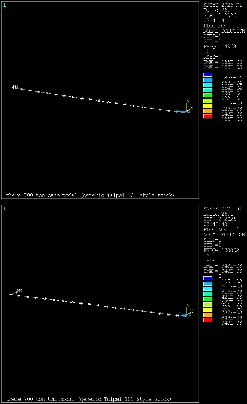
That verification deck earns a sentence, because on this machine plain batch Ansys Mechanical APDL has occasionally stamped a structural run “verification only.” We gate against it: a tiny probe model solves first and the job aborts if the license banner appears. It did not — forcing the Mechanical Enterprise product, all six physics solves ran for real, with no verification banner and no solver errors. The mode shapes come out of the solver’s own eigenvalue extraction, and they already carry the first piece of validation.
One resonance becomes two
The clearest way to see a tuned mass damper work is to sweep a steady wind load slowly across a band of frequencies and watch how far the crown drifts at each one. The bare tower does what a lightly damped resonator always does: almost nothing until you approach 0.15 Hz, then a tall, narrow spike as the drift runs away to 8.6 m right at resonance. That single spike is the whole vulnerability — one frequency where the building is dangerously easy to move.
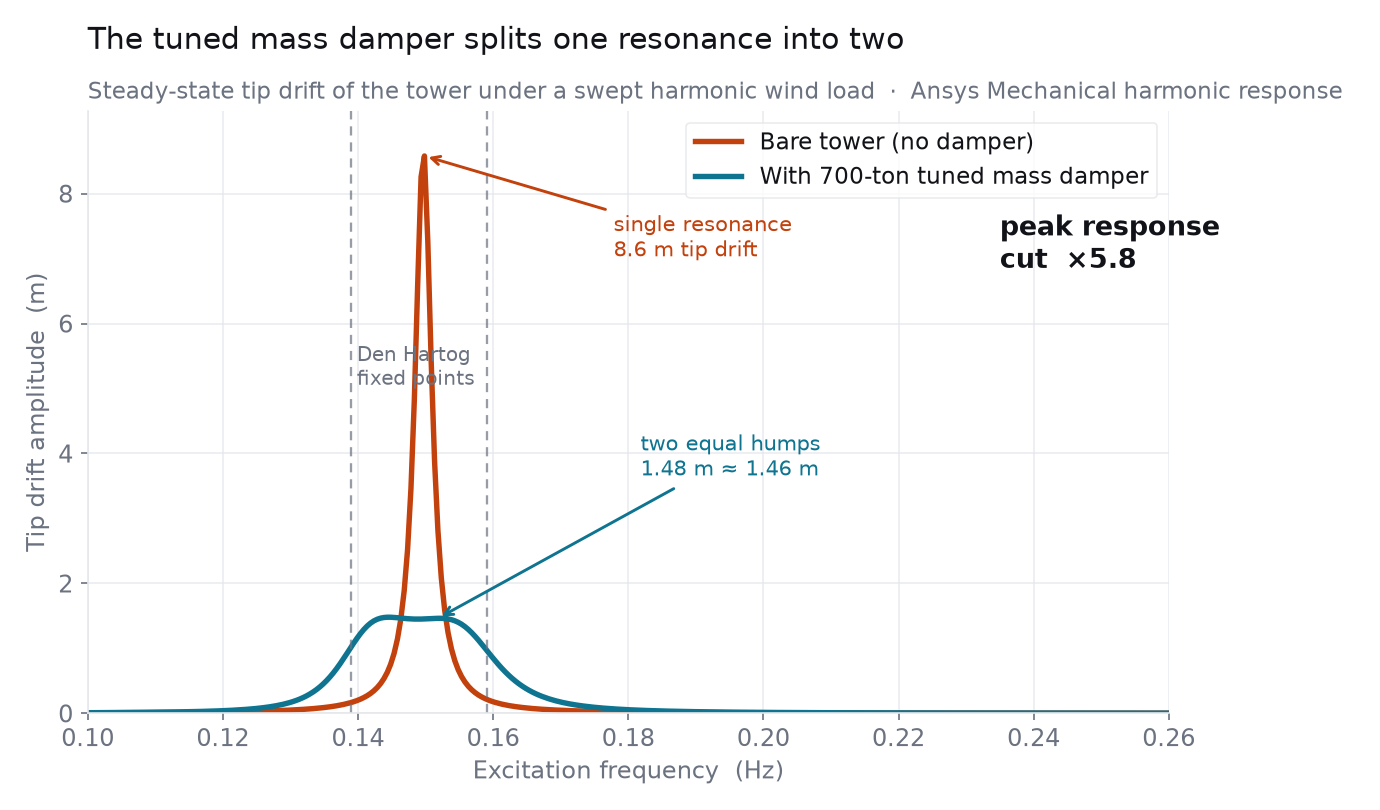
With the damper attached, that spike is gone. In its place are two low, broad humps sitting on either side of the old resonance — and, tellingly, they are almost exactly the same height. That equal-peak shape is not a coincidence; it is the specific outcome Den Hartog’s optimum is designed to produce, and the fact that our solve reproduces it — two humps of 1.48 and 1.46 m, straddling the predicted split frequencies of 0.139 and 0.159 Hz — is a strong sign the physics is right. The tower no longer has a single frequency where it is easy to push. The price of that safety is paid entirely by the ball.
Riding out the gust
Frequency sweeps are how an engineer thinks; a gust is what the building actually feels. So we drove both towers with the same 250-second narrowband wind load, ramped up and centered on the sway frequency — a stylized but honest picture of a sustained resonant buffeting. The bare tower does exactly what the swing analogy warns: it rings up, cycle after cycle, until the crown is tracing a 4.3 m arc. The tower carrying the damper barely participates. Its crown sway saturates early and never exceeds 0.87 m — a ×5.0 cut in the peak and a ×3.8 cut in the sustained RMS motion.
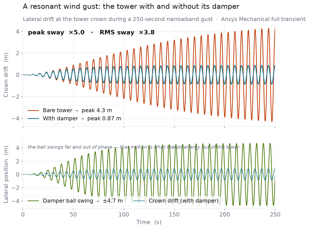
The bottom panel is the whole idea in one line. The ball swings through ±4.7 m — much farther than the tower crown ever moves — and it does it against the tower’s motion. The pendulum has effectively volunteered to be the thing that sways, absorbing the gust’s energy into its own big, damped arc and bleeding it away through the cable’s viscous drag. The building, relieved of the job, stays put.
Trusting the numbers
A converged simulation that is quietly wrong is the usual way this kind of study fails, so it is worth being explicit about why we believe this one. The strongest reason is that the tuning and the finite-element model are independent calculations that agree. The pendulum’s mass, length and damping were fixed by Den Hartog’s closed-form 2-degree-of-freedom theory before the tower was solved. The Ansys model is a full 21-node beam — it knows nothing about that theory. Yet when it is solved it reproduces the theory’s two independent predictions: the fundamental mode splits into a pair at 0.1388 and 0.1588 Hz, within a percent or two of the predicted fixed points, and the harmonic response comes out as two equal humps, which is the tuning’s specific signature and not something you get from a mistuned or mismodeled damper. Agreement between two computations that share no equations is a real check, not a tautology.
The transient reductions land close to, but a little short of, what the simple 2-DOF theory predicts (about ×5.5 peak and ×4.8 RMS). We report the finite-element numbers as they came out — ×5.0 and ×3.8 — rather than tuning the model to match the textbook. In the frequency domain the same comparison runs the other way: the finite-element harmonic peak reduction (×5.8) comes out a touch higher than the closed form (×5.5). The finite-element results straddle the simple theory rather than uniformly beating or missing it — exactly what you expect when a full continuous beam is measured against a lumped two-degree-of-freedom idealization, and a sign that neither result is being bent toward the other. The transient gap in particular is expected and explainable: the theory idealizes the tower as a single lumped mass, while the real gust here is spread across the top seven stories and the tower carries stiffness-proportional (Rayleigh) damping rather than a flat modal 1%. Those differences move the sustained-motion number the most, which is exactly the pattern we see. The direction, the mechanism, and the frequency-domain fingerprint are unambiguous; the last few tenths on the RMS ratio are a modeling-fidelity detail, and we flag it as one.
| Quantity | Den Hartog closed form | Ansys finite element |
|---|---|---|
| Tower sway frequency | 0.150 Hz (target) | 0.1497 Hz |
| Split-mode pair | 0.139 / 0.159 Hz | 0.1388 / 0.1588 Hz |
| Harmonic peak reduction | ×5.5 | ×5.8 |
| Transient peak sway reduction | ×5.5 | ×5.0 |
| Transient RMS sway reduction | ×4.8 | ×3.8 |
| Damper mass ratio | 1.8% (660-tonne ball; pendulum length 11.45 m, damping ratio ~8%) | |
For context — not as our result — Taipei 101’s real 660-tonne sphere is reported to cut the building’s wind-driven sway by something like 30–40%, using a mass ratio far smaller than ours because it is tuned for occupant comfort in everyday winds rather than to knock down a single worst-case resonance. Our larger mass ratio buys a bigger number on one narrowband gust; it is the same physics, dialed to make the mechanism vivid.
Honest scope. This is a representative dynamics model built to make a mechanism visible, not a design-office model of any specific building. The tower is a single planar cantilever “stick” — twenty beam elements carrying lumped floor masses, tuned to a 0.15 Hz sway — with no torsion, no higher-mode wind coupling, no P–Δ or second-order geometric effects, no soil–structure interaction, and linear elastic material throughout. The pendulum is modeled as a linearized small-swing spring–mass–damper, valid for the amplitudes here but not for very large swings. The wind is an idealized narrowband resonant force history, not a CFD wind field, a turbulence spectrum, or an aeroelastic (flutter/galloping) simulation; the real vortex-shedding and buffeting that drive a tower are outside this study. The damper’s mass ratio (1.8%) is deliberately larger than the fraction of a percent a real comfort-tuned skyscraper damper uses, so the reduction factors here are specific to this model and this gust, not general design values. Earthquakes are not modeled: a single-frequency tuned mass damper helps most against the narrowband wind response it is tuned to and does far less against the broadband, multi-mode shaking of a quake, which is a different problem. The Taipei 101 figures are cited as real-world motivation, never as an output of this model. Every simulated number above is read directly from the Ansys results files.
Have a what-if that deserves a real solver instead of a rule of thumb? Some of the most satisfying answers come from taking an offhand question — why is that ball up there, would this actually hold, how much does the damper really buy you — and meshing it until the physics settles the argument. If there is a structure, a flow, or a field you have always wondered about, we would love to talk it through. Rand Simulation is an Ansys (Synopsys) Apex Channel Partner, and this entire study — geometry, mesh, solve, and post-processing — was run end to end by an agentic AI workflow on our own licenses. Innovation Through Insight™.