Why a Transformer Hums at Twice the Grid Frequency
Stand near a substation, a pole-top can, or a big plug-in power supply and you hear the same thing: a flat, steady electrical hum. Hold a phone tuner up to it and, on a 60 Hz grid, the strongest tone sits right at 120 Hz — exactly twice the line frequency, not at it. That is not a coincidence, and it is not the current you are hearing. It is the steel core inside the transformer physically squeezing itself smaller and letting go, 120 times every second, and that tiny breathing motion pushing on the air. We built a representative laminated core in Ansys, drove it with the same magnetic squeeze a real one feels, and watched — as an animation and as real numbers — how much it actually moves and which of its faces you are hearing.
Why 120, and not 60
The whole answer is one line of algebra, and it is worth seeing because it explains the pitch of every transformer you will ever stand next to. The magnetic flux in the core is alternating: it follows the grid, B(t) = B_pk·sin(ωt) with the line running at 60 Hz. The force that pulls magnetized steel together does not follow the flux — it follows the flux squared. Both squeeze mechanisms below are quadratic in B, and squaring is what does the trick:
force ∝ B² = B_pk²·sin²(ωt) = (B_pk²/2)·(1 − cos 2ωt)
Read the right-hand side. There is a steady part, and there is an oscillating part at 2ω — twice the line frequency. Because the force depends on the square of the field, it never cares which way the current is flowing: the steel is pulled just as hard when B points up as when it points down, so the squeeze happens twice per electrical cycle. On a 60 Hz grid that is 120 Hz (on a 50 Hz grid it is 100 Hz). That is the entire reason the hum sits at twice the wall frequency, and it is exact — no simulation required to prove it, only to find out how loud it gets.
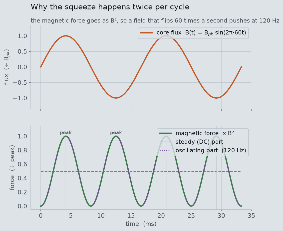
B(t) swings up and down at 60 Hz. Bottom: the magnetic force, which goes as B², peaks twice for every single swing of the flux — it splits cleanly into a steady offset plus a 120 Hz oscillation. That 120 Hz term is what shakes the core.Two ways the same field squeezes the core
A no-load transformer core is squeezed by two distinct effects, and the everyday hum is the sum of both. The first is the magnetic (Maxwell) force: wherever flux is carried through steel, the field exerts a stress of order B²/2µ₀ that pulls the material together. Across our limb’s 0.008 m² flux cross-section at a 1.6 T working flux, that closed-form Maxwell stress works out to a peak pull of 8.15 kN — nearly a ton of force — and its 120 Hz component, the part that actually shakes things, has an amplitude of 4.07 kN on each limb. We anchor the flux to 1.6 T because that is squarely inside standard power-transformer design practice (cores are run at roughly 1.5–1.7 T), which keeps the force magnitude physical. This magnetic pull enters the structural solve as a per-limb and per-yoke force amplitude set by that design flux, not as a spatially mapped field — a deliberate, one-way idealization spelled out in the scope note below.
The second effect is magnetostriction: grain-oriented silicon steel literally changes length when it is magnetized. The strain is small — a few parts per million at working flux — but it happens over the whole core, 120 times a second, and in a tightly-built gapless core it is usually the dominant source of the no-load hum. We take the strain magnitude from published grain-oriented-steel data (about 2 ppm at this flux) and apply it the standard way, as an equivalent thermal strain imposed on the steel at 120 Hz. Both effects are even in B, both land at 120 Hz, and both are applied together to drive the structural solve.
Building the core, and running it for real
The core is a generic single-phase core-type transformer: a rectangular laminated window — two vertical limbs joined by two horizontal yokes — with copper windings on the limbs, the most recognizable transformer frame there is. In Ansys it is a solid SOLID187 tetrahedral mesh of the window frame (11,696 nodes, 9,265 elements), given the orthotropic elastic properties of a lamination stack: stiff in the plane of the sheets (200 GPa) and more compliant through the stack (120 GPa), which is what a bonded pile of thin sheets actually behaves like. The copper winding is carried as lumped MASS21 mass on the limbs, and the core is clamped at its feet as a representative mounting.
One sentence on how it ran, because it matters for trusting the numbers. On this machine, plain batch Ansys has occasionally stamped a structural run “verification only,” which would quietly invalidate the results. We gate against it: a tiny probe model solves first and the job aborts if that banner appears. It did not — forcing Mechanical Enterprise, the modal, free-free and harmonic solves all ran for real, with no verification banner and no solver errors. Every number below is read straight off the Ansys results file.
The core’s own frequencies are far from the hum
Before asking how hard the core breathes, you have to ask what it wants to do — its natural frequencies. A modal analysis (Block Lanczos) gives them directly, and the answer is decisive: the lowest natural frequency of this clamped core is 278 Hz, and the mode that actually looks like the core “breathing” — the window ovalizing in and out — sits all the way up at 1332 Hz. A free-free cross-check (the core floating, unclamped) puts its first elastic mode at 908 Hz, the same story. Every mode is far above the 120 Hz drive.
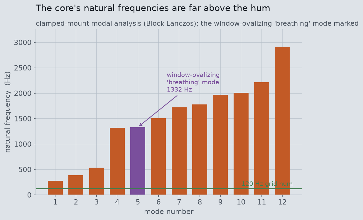
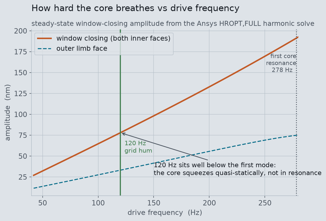
That gap is the whole character of this transformer’s hum. Because the drive sits well below the first resonance — the ratio is only 0.43 — the core cannot ring. It is driven in its quasi-static regime, where the structure simply follows the force stiffly, in step, with no resonant amplification. It is the difference between pushing a child on a swing at exactly their natural rhythm and just leaning on the swing steadily: same push, wildly different motion.
How much it actually breathes
The harmonic response solve answers “how much” directly — a full frequency sweep from 40 to 280 Hz, driven by the combined magnetic force and magnetostrictive strain, giving the steady-state amplitude at every frequency. At 120 Hz the window closes and opens by about 78 nanometers across, and the broad faces of the core move out and back by up to about 1 micron at their liveliest points. That is genuinely tiny — a fortieth of the width of a human hair at most — and yet a whole core doing it 120 times a second, coupled to the air and often to a steel tank, is exactly loud enough to hear across a parking lot.
Which surfaces you actually hear
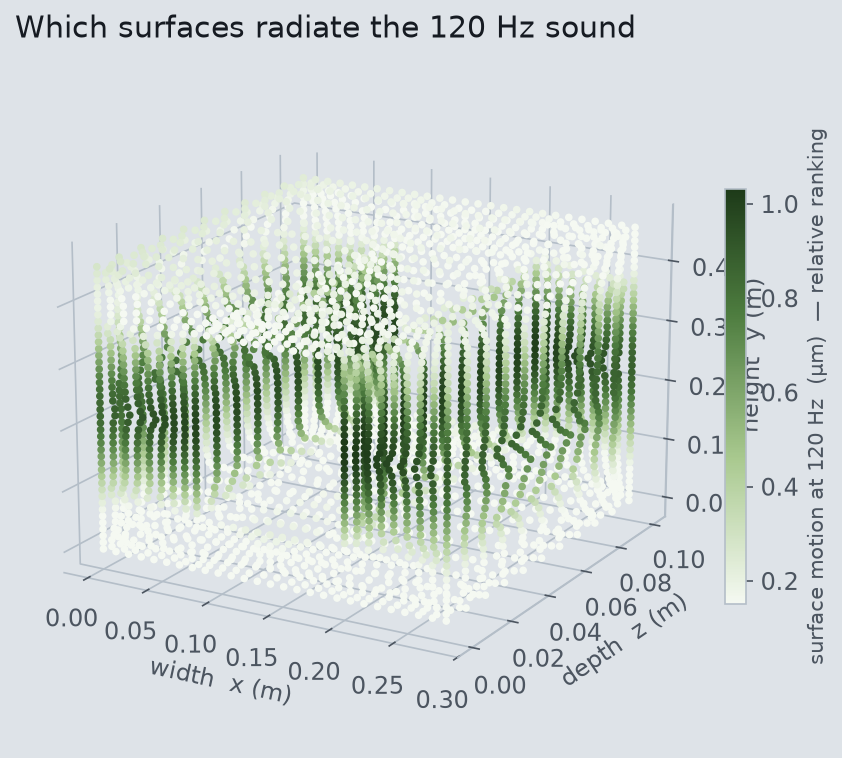
Sound comes off the fastest-moving, broadest surfaces, so the harmonic solve also ranks the core’s outer faces by how much they move at 120 Hz. The broad flat faces of the laminations — the largest-area surfaces of the frame — carry both the most area and the highest peak motion (around 1 micron), which makes them the core’s loudspeaker. The top and bottom yokes move least (well under a tenth of a micron on average). This is a relative ranking of surface motion, the honest thing a structural solve can say about radiated sound; turning it into an absolute decibel level needs a dedicated acoustic radiation solve, which is a separate study.
Trusting the numbers
The strongest reason to believe this study is that its independent anchors all agree. The 120 Hz doubling is exact algebra, not a fitted result. The 1.6 T flux we drive it at is standard design practice, and the 2 ppm magnetostriction comes from published silicon-steel data — neither was tuned to produce a nice answer. The clamped and free-free modal solves tell the same story about where the resonances are, and a back-of-envelope single-degree-of-freedom estimate lands on the same modest amplification the full harmonic sweep shows. And the honesty cuts the other way too: the interesting finding here is a negative one — this particular core does not resonate at the hum frequency, it squeezes quasi-statically — and we report that as it solved rather than forcing the geometry until a mode landed on 120 Hz. That off-resonance behavior is itself the point: it is why transformer designers work hard to keep core mechanical modes away from 120 Hz, and why the ones that fail to are the loud ones.
Honest scope. This is a representative model built to make a mechanism visible, not a design-office model of any specific product; the geometry is self-authored and generic, with representative grain-oriented-steel and copper properties. The electromagnetic-to-structural coupling is deliberately one-way and component-level: the magnetic pull is applied as per-limb and per-yoke force amplitudes and the magnetostriction as a whole-core equivalent strain, not as a two-way node-mapped magneto-mechanical co-simulation or a co-solved spatial force-density field. The magnetic force magnitude is anchored to a standard 1.6 T core design flux through the closed-form Maxwell stress rather than mapped from a solved field distribution, and the magnetostriction magnitude is taken from published silicon-steel λ–B data rather than a solved nonlinear magneto-elastic law. The study models the no-load core hum only: saturation harmonics at 240 and 360 Hz, core-loss and hysteresis heating, load-current winding forces, and the exact clamping, tank, oil and cooling-fin acoustics are not modeled, and the mounts are represented as clamped feet. “Which surfaces radiate” is answered as a relative surface-motion ranking; an absolute A-weighted sound level or a full acoustic radiated-field solve is out of scope. Every simulated number above — the natural frequencies, the breathing amplitudes, the surface-motion ranking — is read directly from the Ansys results file, and the modeled core’s off-resonance behavior is reported exactly as it solved.
Have a what-if that deserves a real solver instead of a rule of thumb? Some of the most satisfying answers come from taking an everyday question — why does that thing hum, would this actually hold, how much does that really move — and meshing it until the physics settles the argument. If there is a structure, a flow, or a field you have always wondered about, we would love to talk it through. Rand Simulation is an Ansys (Synopsys) Apex Channel Partner, and this entire study — geometry, mesh, solve, and post-processing — was run end to end by an agentic AI workflow on our own licenses. Innovation Through Insight™.