How Hot Is Too Hot for Train Tracks?
Every serious heatwave produces the same photo: a railroad track that was dead straight on Monday lying in a lazy S-curve on Friday, rails and ties swept sideways together as if a giant had dragged a thumb across them. Railroaders call it a sun kink, and nothing hit it — the bend was pushed there by sunshine. Modern rail is welded into ribbons and anchored so it cannot expand, so a hot rail has nowhere to put its extra length except into compression, and past a threshold temperature it buys relief the only way it can: by buckling sideways through the gravel. A reader asked us to find that threshold, so we built a few hundred feet of anchored track in Ansys, gripped it with realistic ballast, and turned up the temperature until it let go.
A Rail That Cannot Expand
Old-fashioned jointed track left small gaps every 12 meters precisely so rail could breathe with the seasons — the clickety-clack was thermal engineering. Continuous welded rail deleted the gaps for a smoother, stronger, cheaper-to-maintain track, and inherited a physics problem in exchange: a welded ribbon anchored to the ties cannot get longer. Heat it above the neutral temperature — the temperature at which it was fastened down stress-free — and the blocked expansion becomes axial force. The relationship is as clean as structural mechanics gets: P = EA·α·ΔT. For our two 136RE-class rails that is about 20 kN per °C per rail, roughly two tons of extra squeeze for every degree Celsius. A 40 °C rise above neutral puts 1.6 meganewtons — some 360,000 pounds — of compression into the track panel.
A straight, compressed elastic ribbon is a loaded spring. Below a threshold, the ballast’s grip on the ties holds the line straight and nothing visible happens. Above it, any small alignment defect — a couple of centimeters of wiggle left over from maintenance or a soft spot — grows explosively, and the panel trades its stored axial strain energy for a sideways lunge several tens of meters long. That is why the answer to “how hot is too hot” is never a single number on a thermometer: it is a temperature rise above neutral, filtered through how well the ballast holds the track and how straight the track was to begin with. This study measures all three dependencies from the solver.
The Model: a Beam, 800 Nonlinear Springs, and a Deliberate Flaw
The track panel is a 120 m (about 400 ft) tangent stretch, modeled the way the classic rail-buckling literature does it: one BEAM188 beam carrying the combined section of two 136RE rails (AREMA section values — area 172 cm², lateral bending inertia 2 × 14.7 in⁴), 400 elements at 0.3 m — more than 30 elements per buckle half-wave. Motion is confined to the horizontal plane, where sun kinks actually happen.
The ballast is the heart of the model, and it is deliberately not a linear spring. Each of the 401 nodes carries a COMBIN39 nonlinear spring with the characteristic measured in single-tie push tests (the Volpe/FRA work of Kish and Samavedam, and the European ERRI D 202 program): resistance rises to a peak at about 6 mm of lateral displacement, then plateaus — the gravel grips, then yields and keeps sliding at roughly constant force. That peak resistance is the swept parameter: 5 to 20 kN per meter of track, spanning the published band from freshly tamped, maintenance-disturbed track to fully consolidated, traffic-hardened track. In plain terms, the sweep asks the same question six ways: how hard does the gravel hold the ties?
Finally, the flaw. Perfectly straight beams buckle only in textbooks; real thresholds are set by real crookedness. We seeded a sinusoidal lateral misalignment — one 10 m half-wave, 20 mm of amplitude, a realistic minor line defect — into the track’s stress-free shape, and re-ran the mid-ballast case at 10 and 40 mm to show how much the answer moves. The rail ends are held axially (the far track anchors the panel), which slightly stiffens the response compared with modeling kilometers of feed-in rail on either side; we accept that small conservatism-in-reverse and disclose it in the scope box below. One more honesty note on how it ran: plain batch Mechanical APDL on this machine has occasionally stamped structural runs “verification only,” so a tiny probe deck solves first and the pipeline aborts if the license banner appears. It did not — all eleven solves ran on the full Mechanical Enterprise solver, and every number below is read from those results files.
First, the Ideal Answer — So We Can Watch It Fail
Before trusting a nonlinear solver anywhere near a limit point, we anchor it. Replace the elastoplastic ballast with its initial elastic stiffness and ask for the classical eigenvalue buckling load: an infinite beam on an elastic foundation has the closed-form answer Pcr = 2√(k·EI), which for the mid ballast converts to a critical temperature rise of 106.9 °C. The Ansys eigenvalue solve on the same idealization says 107.9 °C — agreement to 0.9%, with the beam, foundation, and thermal-prestress plumbing all in the loop. That number is deliberately unphysical — elastic gravel that never lets go, track with no flaw — and its job is to be the upper bound the honest model falls away from.
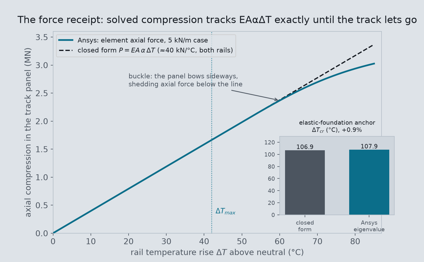
P = EAαΔT — the pre-buckle agreement is better than 0.01%, and the departure below the line is the buckle, the panel bowing sideways and shedding load. Inset: the eigenvalue anchor — Ansys reproduces the beam-on-elastic-foundation closed form within 0.9%.Then the Real Answer: Ramp Until the Equilibrium Disappears
The real runs switch on large-deflection geometry, the elastoplastic ballast, and the 20 mm flaw, then ramp the rail temperature and track the equilibrium path — temperature against lateral deflection at the crest of the defect. The path is the whole story. It rises gently while the ballast holds (millimeters of growth), steepens as the gravel approaches its plateau, and then reaches a limit point: a temperature above which no straight-ish equilibrium exists at all. Past it, the panel has to jump to the only equilibrium left — the buckled one. That limit temperature is ΔTmax, the buckling threshold track engineers design against.
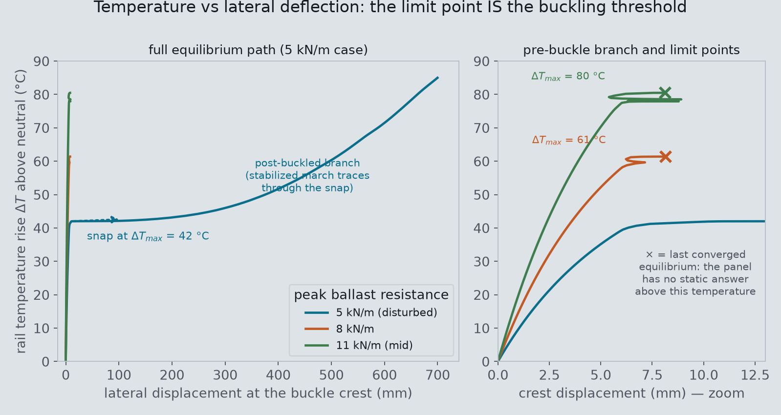
The three soft cases die exactly the way stability theory says they should: the solver bisects its step smaller and smaller and still cannot find equilibrium, because above the limit point there is none to find. We read ΔTmax as the last converged temperature. The weakest case is the show-off: with only 5 kN/m of grip, nonlinear stabilization carries the solution through the snap, and the static path itself traces the jump — ten millimeters to a tenth of a meter with almost no temperature change, then a stable post-buckled track bowed 0.7 m sideways. One honest limitation of that stabilized march: it steps over the unstable branch rather than tracing it backward, so the classical companion number ΔTmin — the lower “safe” temperature below which no buckled equilibrium survives — is not resolved by this study, and we say so rather than estimate it.
The Headline Curve: Threshold Versus Grip
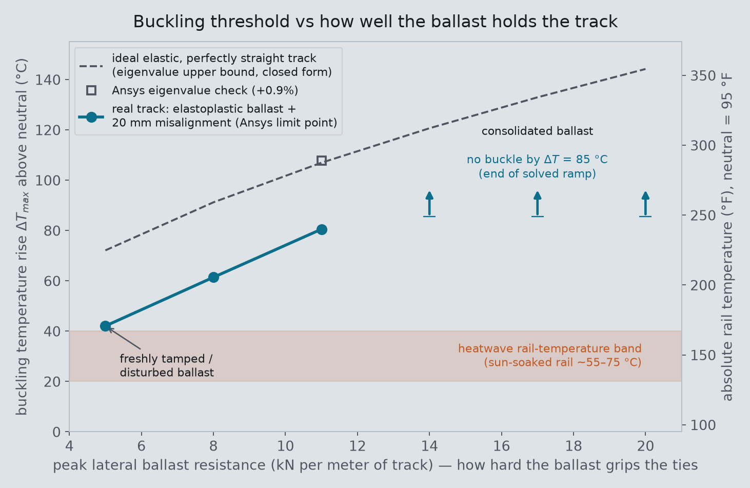
Read the curve against the shaded band and the seasonal news story explains itself. Consolidated track — years of traffic pressing the ballast shoulder tight — carries a threshold far above anything weather can deliver: our 14–20 kN/m cases were still holding at ΔT = 85 °C when the solved ramp ended, and their eigenvalue bounds sit higher still. But tamp the track — surfacing, lining, tie replacement all disturb the ballast and can halve its lateral grip until traffic re-consolidates it — and the threshold drops into the band a heatwave actually reaches. At 5 kN/m, ΔTmax = 42 °C: over a 35 °C neutral, that is a 77 °C (170 °F) rail on a day when sun-soaked steel plausibly gets there. This is precisely why railroads issue slow orders on freshly maintained track in summer, and why heat orders exist at all: the same afternoon that is harmless to one mile of railroad is a buckling risk to the mile that was tamped last week. The trend and the mechanism match the Volpe/FRA CWR-buckling framework this model borrows its ballast curves from; our fixed-end idealization sits on the stiff side of it, so we frame the agreement as consistency with the published picture, not a reproduction of any specific test.
How Straight Is Your Track? The Other Lever
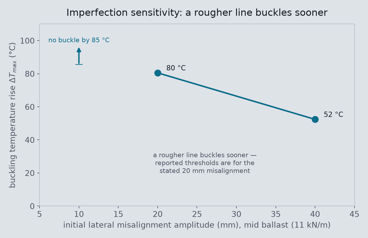
Buckling thresholds are not properties of a track; they are properties of a track plus its worst flaw. A 40 mm misalignment — still only a subtle wave a passenger would never feel — costs the mid-ballast track 28 °C of margin, which is the difference between “impossible weather” and “a bad August.” Combined with the ballast curve, this is the whole risk picture in two charts: disturbed ballast or degraded alignment each eat the margin; together — which is exactly the state of a line mid-maintenance — they eat it twice.
The Snap Itself
Everything above is quasi-static — the honest way to locate a threshold, but not what a buckle looks like. So the final run hands the mid-ballast case to the implicit-dynamic solver: temperature ramped smoothly over ten seconds, inertia and damping live. The panel stays visually straight to 70-odd degrees while the crest creeps through single millimeters — then, between ΔT = 77.7 and 79.3 °C, it dynamically snaps: 0.34 m sideways in about a quarter of a second, an overshoot, a shudder, and a settle onto the buckled shape at 0.30 m. That solved motion — not an artist’s morph — is the hero animation, drawn at true scale. The dynamic event completes by 79.3 °C, within about 3% of the static limit point at 80.5 °C — the two solvers agreeing on the threshold from opposite directions, statics by losing equilibrium and dynamics by falling off it.
Trusting the Numbers
Three independent checks hold this study up. First, the force law: on the straight, pre-buckle branch the solved axial compression tracks P = EAαΔT to better than a hundredth of a percent — the load path into the buckle is exact, not approximately right (the largest-defect case departs from the line earliest, because it starts bowing soonest, which is the physics rather than an error). Second, the eigenvalue anchor: on the linear idealization, the finite-element critical temperature lands within 0.9% of a closed form it shares no code with. Third, internal consistency: the static limit point and the dynamic snap temperature agree within a few percent on the same configuration, and the threshold moves with ballast strength and imperfection amplitude in the direction and rough proportion the published CWR stability literature says it must. What we deliberately did not do is tune anything toward a target: the section, ballast curves, and defect were fixed from published values before the first solve, and the thresholds are reported as they came out.
Honest scope. This is a representative stability model of a generic tangent track, built to make a mechanism measurable — not a design or safety analysis of any railroad’s territory. The track panel is a single beam carrying the combined two-rail 136RE section on nonlinear lateral springs; ballast behavior is the published single-tie push-test characteristic (peak resistance plus plateau), not discrete stones. The rail ends are axially fixed rather than fed by kilometers of adjacent track with longitudinal fastener slip, which slightly stiffens the response and raises the thresholds relative to an infinite-track idealization. Buckling temperatures are quoted as rises above a stated neutral temperature and for a stated misalignment (20 mm primary; 10 and 40 mm sensitivity) — real thresholds are lower for rougher track, and neutral temperature itself drifts over a rail’s life, which is cited as the practical uncertainty it is. No vehicle is on the track: train-induced uplift and lateral forces usually help trigger real buckles and would lower these thresholds. Tangent track only — curves buckle earlier. Tie-to-rail frame torsional resistance is neglected (mildly conservative the other way); vertical bending and uplift are excluded (in-plane lateral buckling only); the rail temperature is prescribed and uniform, not solved from weather, and the rail-versus-air temperature gap is taken from published measurements. The stabilized static solutions step over the unstable branch, so the lower safe-temperature limit ΔTmin of the classical analyses is not resolved here. Consistency with the Volpe/FRA (Kish & Samavedam) buckling framework is claimed qualitatively; no specific published test is reproduced. Every simulated number above is read from the Ansys results files of this study’s eleven solves.
Wondering where your own margins actually are? The satisfying thing about this question was that the folklore — “tracks buckle when it’s hot” — hides a design curve: two levers, ballast grip and alignment, that move the failure temperature by a factor of two. If your product or infrastructure has a threshold you have only ever known by rule of thumb, a nonlinear stability solve can turn it into a number with receipts. Rand Simulation is an Ansys (Synopsys) Apex Channel Partner, and this entire study — geometry, springs, solves, and post-processing — was run end to end by an agentic AI workflow on our own licenses. Innovation Through Insight™.