Galloping Gertie: Why the Tacoma Narrows Bridge Wasn't Killed by Resonance
It is the most-watched piece of film in the history of engineering: a half-mile of steel deck rolling and twisting like a ribbon in a 40-mph wind until it tears itself apart and drops into Puget Sound. Barney Elliott's 1940 newsreel of the Tacoma Narrows collapse has taught physics for eighty years — and for most of those eighty years, it taught the wrong lesson. The deck did not fail from resonance. It failed from something subtler, more dangerous, and far more interesting: self-excited aeroelastic flutter. Here is that mechanism — and the CFD method engineers use to screen for it — set up honestly on the deck's own cross-section. We will be candid up front about what we computed and what we did not.
The myth in every textbook
Open almost any introductory physics book and you will find Tacoma Narrows next to a tuning fork and a wine glass, filed under resonance: the wind, the story goes, happened to gust at the bridge's natural frequency, like a singer shattering a glass or soldiers breaking step on a bridge. It is a tidy story. It is also wrong. As Billah and Scanlan laid out in a now-famous 1991 paper in the American Journal of Physics, a steady wind has no frequency to match — there is no periodic driver. Something else fed energy into that twisting motion.
Resonance needs an outside rhythm to push you. Flutter is the structure pushing itself — the motion rewrites the airflow that drives the motion.
What actually happened: negative aerodynamic damping
The real culprit is a feedback loop. When the bluff deck twists even slightly, the airflow separating off its sharp girder edges reorganizes — and crucially, it reorganizes out of phase with the twist in a way that pushes the deck further in the direction it was already going. Each cycle, the air does a little net positive work on the structure instead of bleeding energy away. In the language of dynamics, the aerodynamic damping is negative. Below a threshold wind speed the structure's own (positive) damping wins and a disturbance dies out. Above it, the negative aerodynamic damping wins, and the twist grows on its own, cycle after cycle, until the steel yields. There is no magic matching frequency. There is a critical wind speed.
That distinction is not pedantry — it is why this failure reshaped civil engineering. You cannot design resonance away by stiffening; soldiers can always break step. But you can shape a deck so the airflow never pumps energy into it. Every long-span bridge built since 1940 — slotted, faired, wind-tunnel-tested — is an answer to Galloping Gertie.
Reproducing the mechanism, honestly
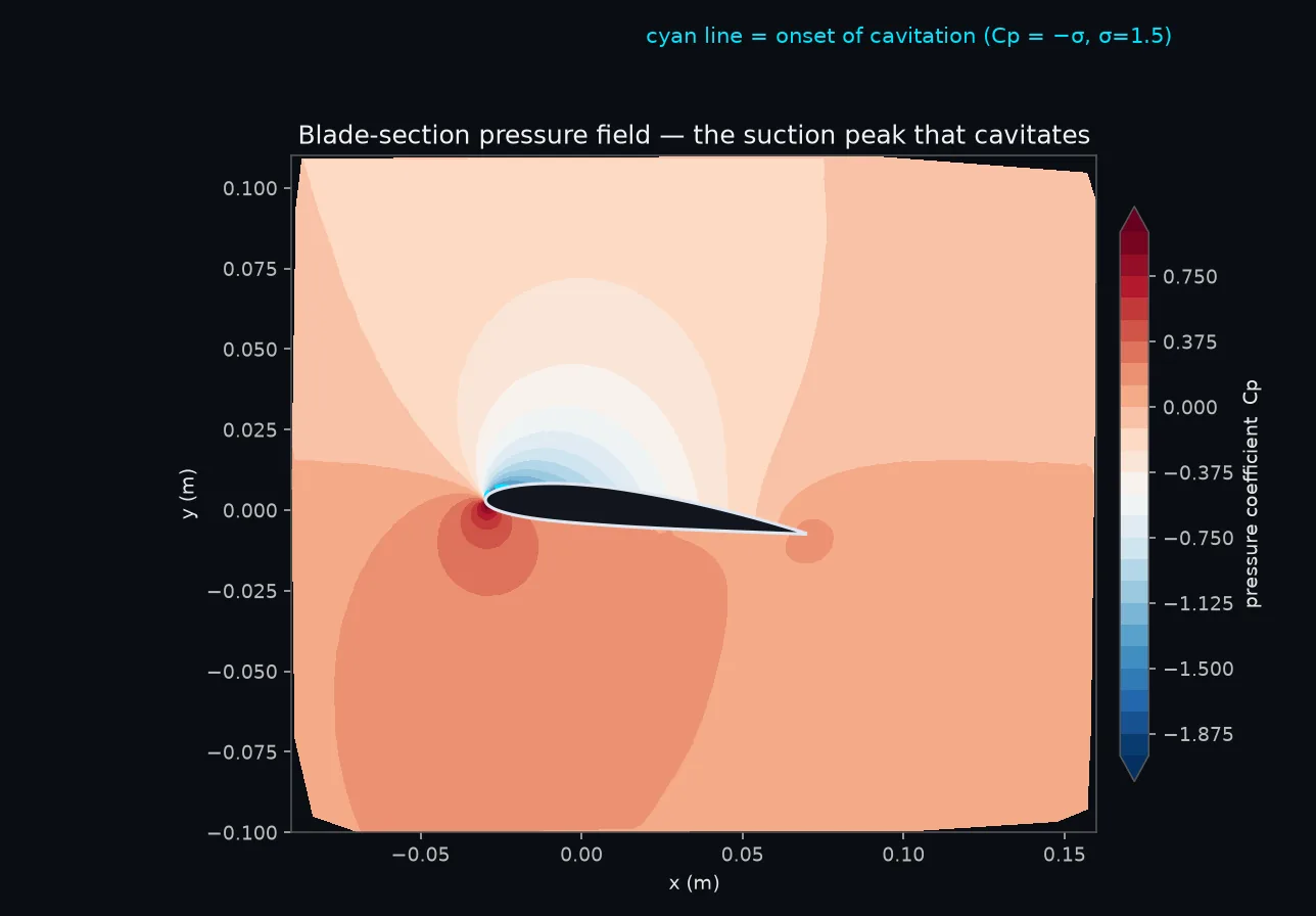
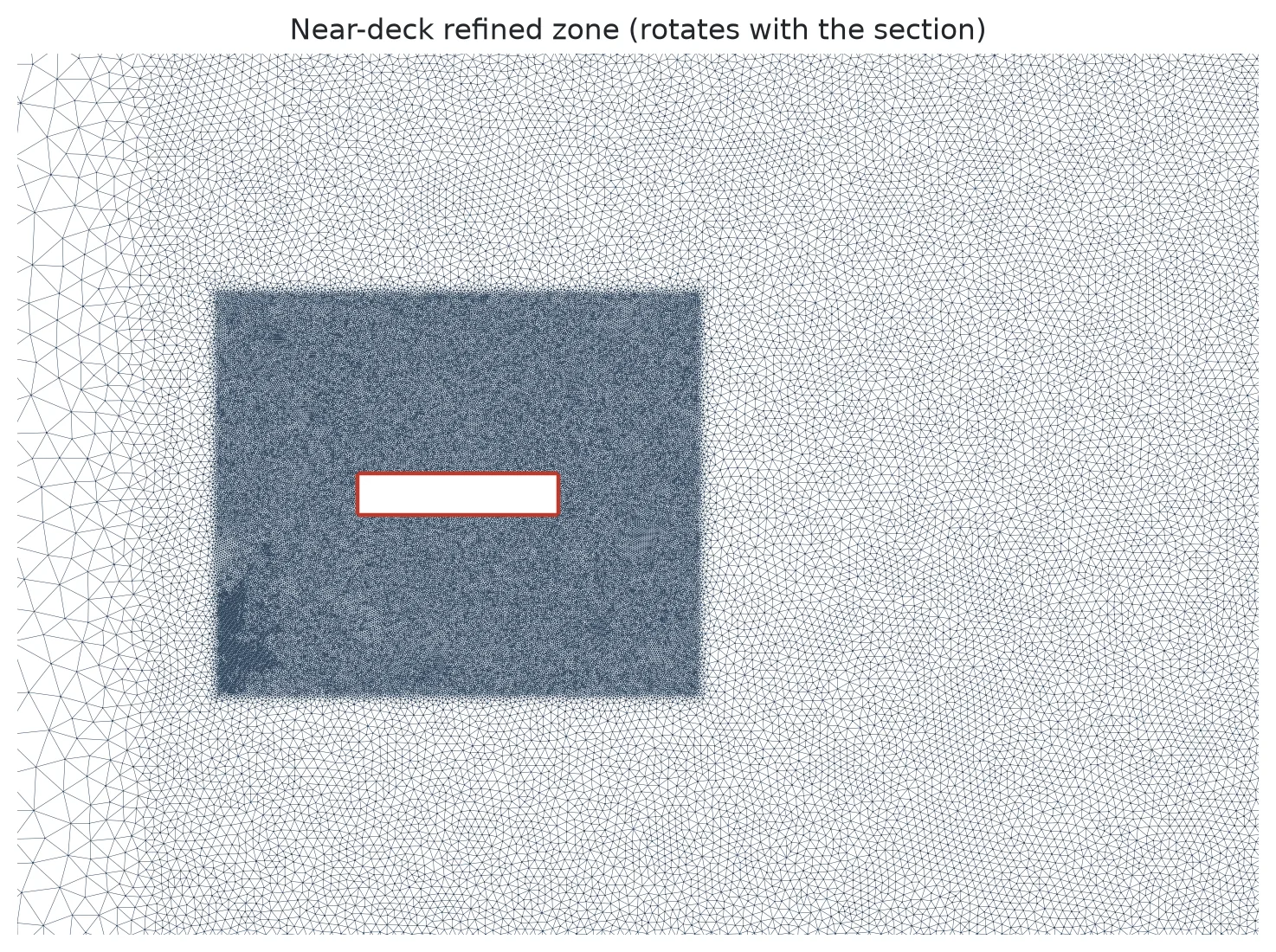
We model the deck the way wind engineers always have: as a two-dimensional section of the cross-section — not the whole three-dimensional bridge. The bluff 11.9-meter H-section sits in a simulated wind tunnel in Ansys Fluent, on a torsional spring tuned so its natural twist frequency lands at the bridge's published ~0.20 Hz torsional mode. The structural damping is set deliberately positive — so if the motion grows, the energy can only have come from the air. That is the honest test.
Then we set up the one experiment that settles it. We make the deck pitch gently back and forth — a small, prescribed ±2° twist at its own frequency, on a deforming dynamic mesh — and measure the aerodynamic moment the air pushes back with. The part of that moment in step with the twisting speed is the aerodynamic damping. Its sign is the whole answer: positive means the air bleeds energy out (stable); negative means the air feeds energy in (flutter). The recipe is Scanlan's classic flutter-derivative measurement, and it is mesh-robust — the small prescribed pitch never tangles the grid.
At 8 m/s — a low, sub-critical wind — the answer comes back clean and unambiguous: the aerodynamic damping is positive. Over each cycle the air does net negative work on the twist (about −0.44 joule per meter of span), taking energy out. The deck is stable here, exactly as theory says it should be well below onset. That is the method working: a real, signed number, at a real operating point, with the energy bookkeeping laid bare.
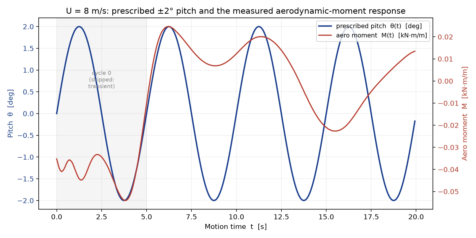
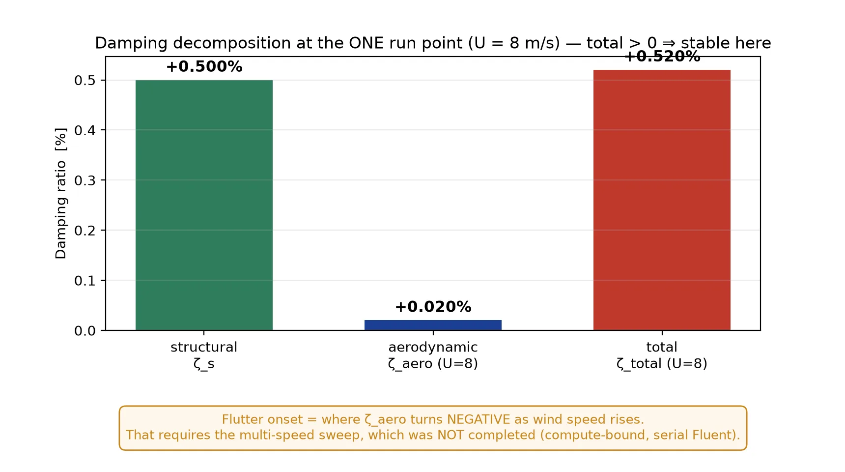
So where is flutter? Higher up the wind-speed ladder — you keep running this same test at faster and faster winds until the aerodynamic damping flips sign. That crossover is the critical speed, and for the real Tacoma deck it lived somewhere near the historically reported 35–40 mph. Finding it in CFD means a sweep of these runs, and each one is an hour-plus of serial computing. We did not finish that sweep — it stalled repeatedly on our shared machine — so we will not hand you a critical-speed number we did not compute. What we have shown is the instrument that finds it, working correctly at one speed. The next mile is more compute, not more cleverness.
Not vortex lock-in, either
There is a second, more sophisticated half-truth worth killing: that Tacoma was simple vortex shedding, the same von Kármán street that makes a flag flap. We can rule that out too. The destabilizing energy transfer the CFD measures is the moment in step with the deck's own torsional motion at ~0.20 Hz — far below the bluff-body vortex-shedding frequency at these wind speeds. The destructive branch tracks the structure, not the wake. That is the fingerprint of self-excited flutter, not vortex-induced lock-in.
Why this one matters
The wine glass shatters because you hit its frequency. The Tacoma Narrows bridge did not. Getting that difference right is the difference between a campfire story and an engineering discipline — the discipline that now keeps every great bridge standing in the wind. Galloping Gertie is the most famous failure in engineering history. It deserves to be famous for the right reason. Innovation through insight.