Will This ECU Survive a GM Engine Bay? Asking GMW3172, Not a Lab
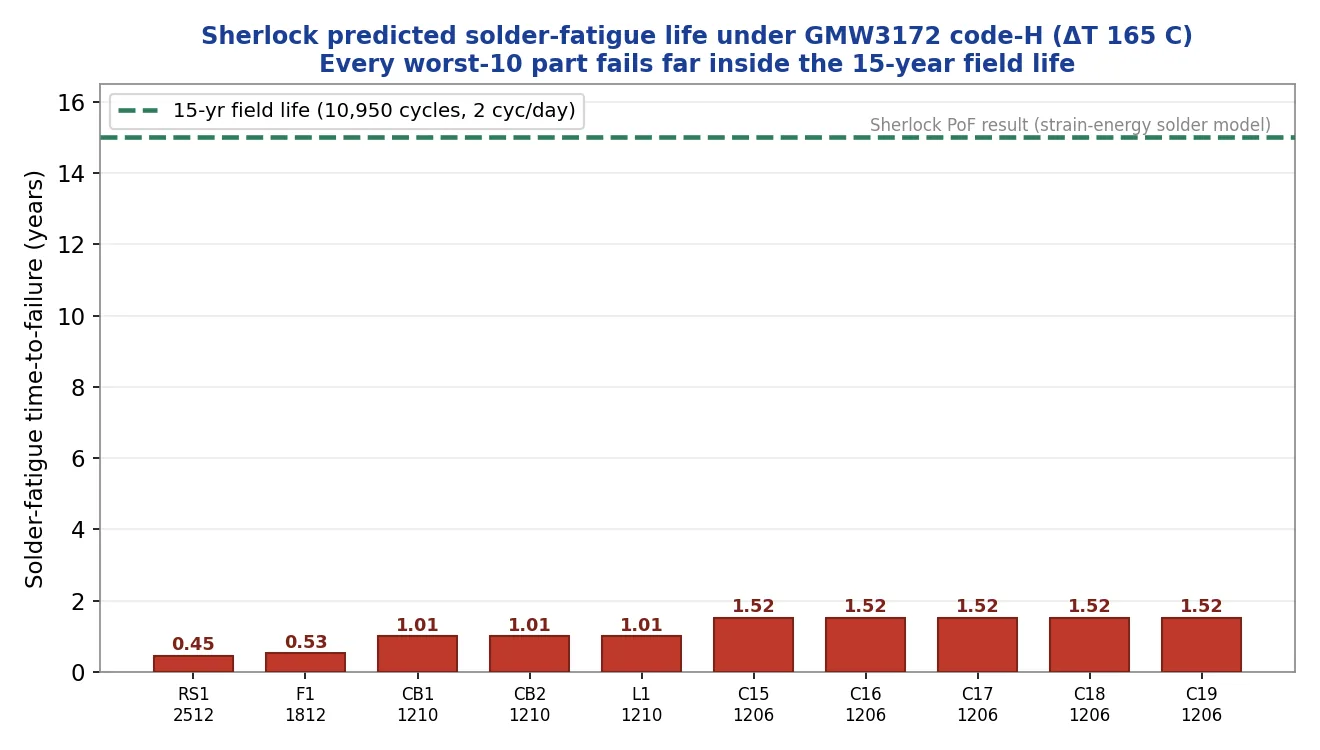
The little black box bolted to your engine lives one of the harshest lives in consumer electronics: baked to +125 °C against the block, snap-frozen to −40 °C on a winter morning, and shaken the whole time. General Motors writes down exactly how harsh, in a spec called GMW3172. We took the same Ansys Sherlock physics-of-failure engine we once aimed at a military board, re-aimed it at GM's under-hood rulebook, and watched the solder joints start failing in under a year — long before the vehicle's 15-year design life.
The spec that governs millions of cars
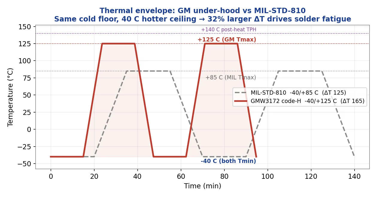
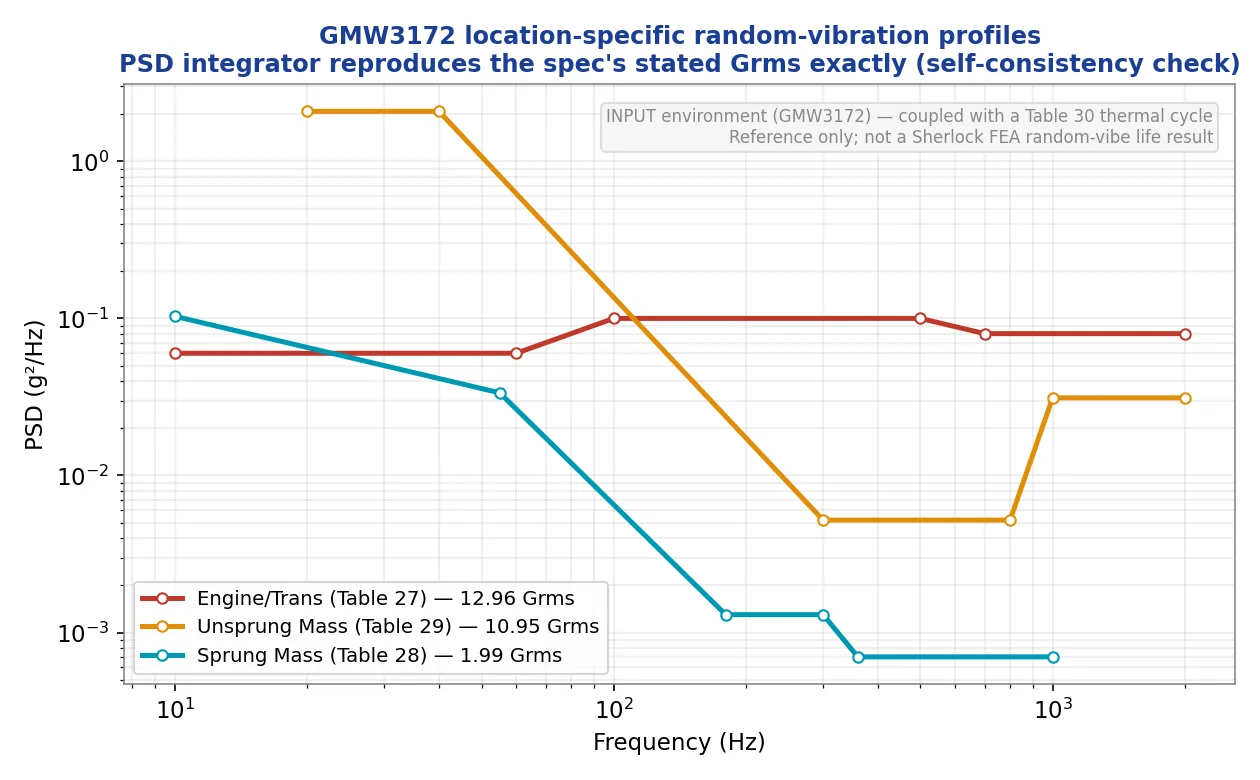
GMW3172 is GM's master environmental-durability standard for every electrical/electronic component in a GM vehicle. The thing that trips up newcomers is that it isn't a single test profile — it's a coding system. You start from where the part is mounted (Table 14), and that location hands you six independent code letters: electrical, mechanical, temperature, climatic, chemical, and ingress. An engine-compartment controller sitting close to the engine earns Temperature code H, and code H is the brutal one: −40 °C to +125 °C, with a +140 °C post-heat soak on top.
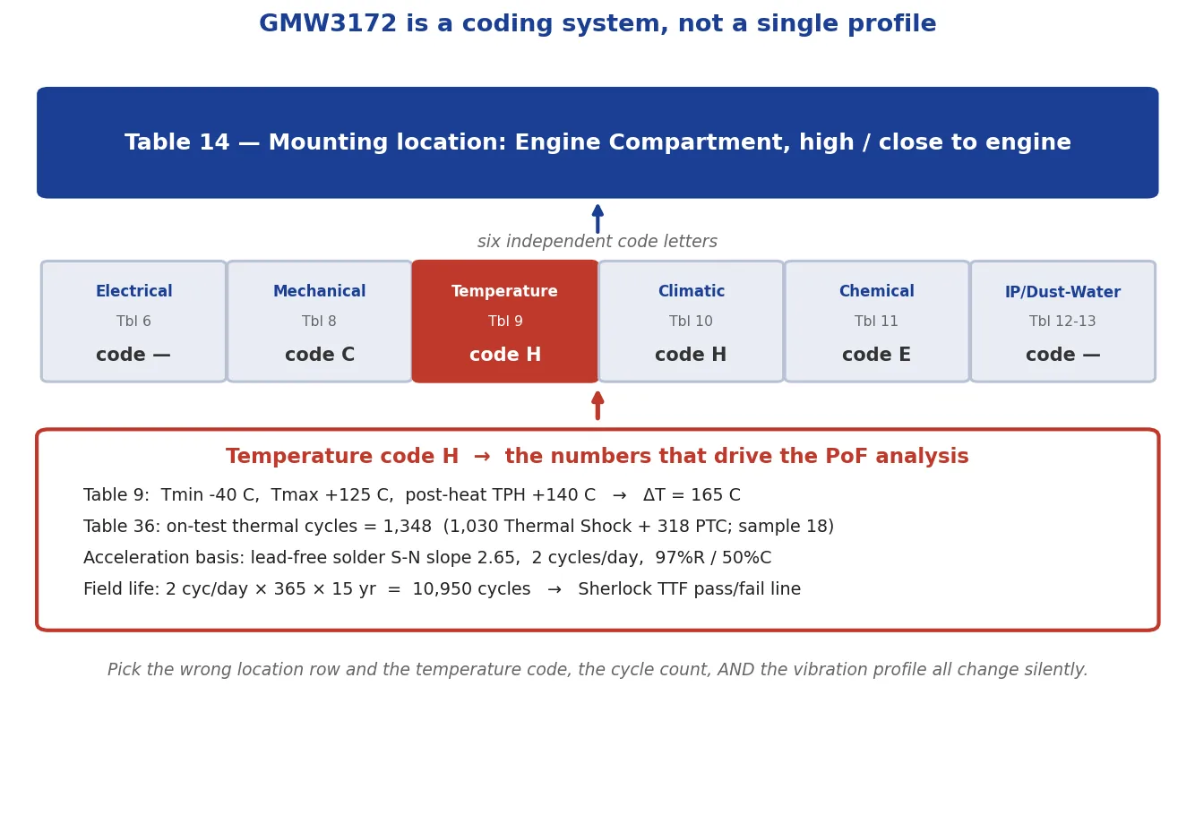
The genius of GMW3172 is that its cycle counts already speak the language of physics-of-failure — a published acceleration model with a lead-free solder S-N slope of 2.65. The spec and Sherlock are, unusually, talking about the same thing.
Why this is a better fit for Sherlock than MIL-STD-810
MIL-STD-810 is a generic environmental-test framework you tailor per program. GMW3172 is different: its thermal-cycle counts bake in an acceleration model. Code H calls for 1,348 combined test cycles to demonstrate 97% reliability at 50% confidence for lead-free solder — and that number is derived with the same Coffin-Manson / Norris-Landzberg machinery Sherlock uses internally. The spec hands you the S-N slope (2.65), the duty cycle (2 thermal cycles a day), and the reliability target. That's why this demo is a cleaner Sherlock story than the military one: the rulebook and the solver agree on what they're measuring.
Two standards, two jobs: the requirement and the method
There's a clean way to think about what we're actually doing. GMW3172 is the requirement — it hands you the loads (the code-H thermal envelope, the location-coded vibration and shock, the cycle counts). The modern standard for how you prove a design against loads like those by simulation is SAE J3168, the first Reliability Physics Analysis (RPA) Recommended Practice written for the aerospace, automotive and defense industries. J3168 is the “reliability by simulation” rulebook: it standardizes the physics-of-failure approach — the same five board-level mechanisms we're computing (solder-joint fatigue from thermal cycling, solder fatigue from vibration, solder failure from shock, plated-through-hole fatigue, and microcircuit wearout). Ansys positions Sherlock as the tool to implement SAE J3168. So this study is, precisely, a J3168-style RPA run against the GMW3172 code-H environment: the requirements come from GM, the method comes from SAE. (To be clear about what we're not saying: J3168 is an SAE Recommended Practice, not a GM-issued spec, and we found no public GM document that names Sherlock by name — tool call-outs like that live in internal supplier specs. GM is publicly moving toward full virtual validation, and that's the gap a J3168 RPA in Sherlock fills.)
Inside the model
The board
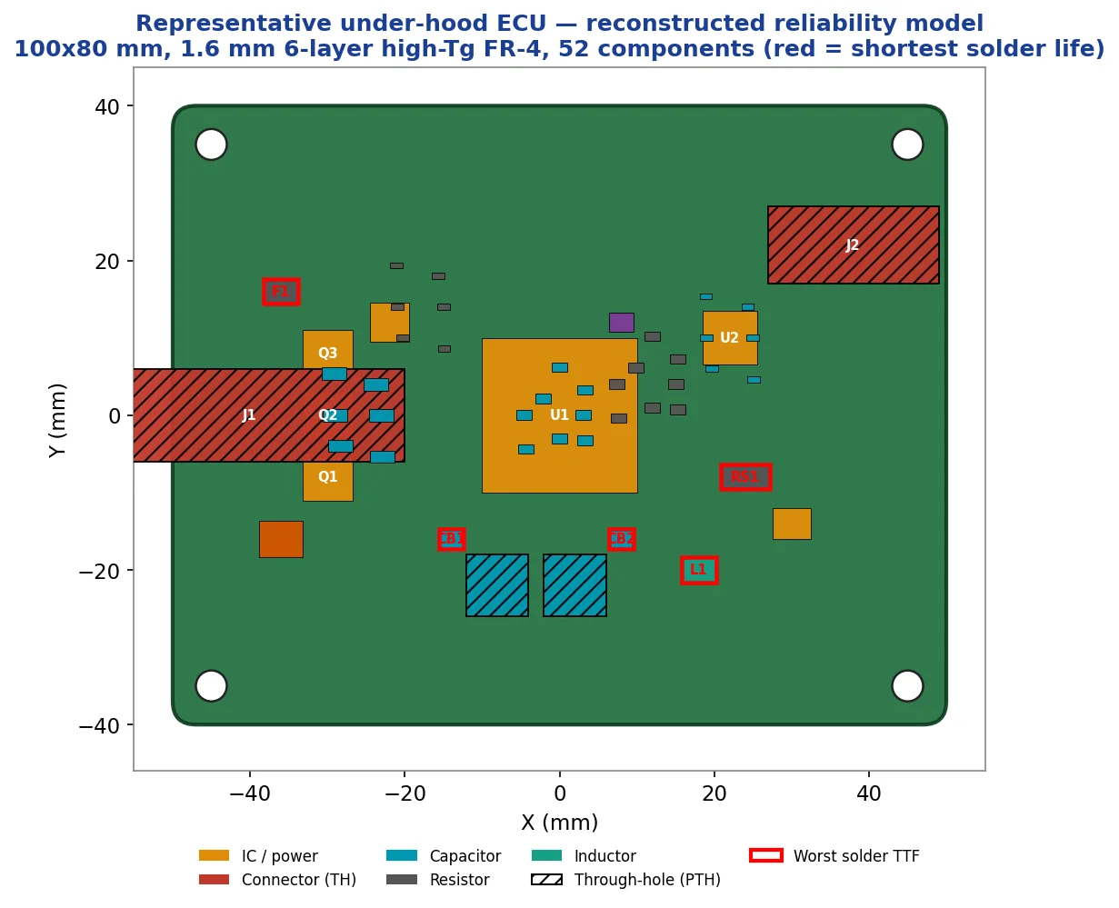
We built a representative under-hood ECU — 100×80 mm, 1.6 mm, six-layer high-Tg FR-4 (Tg ≥ 170 °C, the automotive grade), 2 oz copper, 52 components: power MOSFETs, a 144-pin microcontroller, big leadless ceramic capacitors, a current-sense shunt, and sealed through-hole connectors for plated-through-hole content. It is not a real vendor's manufacturing data — placements and stackup are engineering reconstructions, and the package physics are filled by Sherlock's part library. Under a 165 °C swing the laminate's coefficient of thermal expansion is the dominant lever, so the absolute years are best read as indicative; the robust deliverable is the comparison.
The analysis
We ran the two thermal physics-of-failure analyses that are closed-form and reliable: Solder Joint Fatigue (a strain-energy / Engelmaier-class model) and PTH Fatigue (IPC-TR-579), against a GMW3172 code-H life phase of 10,950 field thermal cycles — that's 2 cycles a day for 15 years. We deliberately kept the spec's 1,348 test cycles separate from Sherlock's independently-predicted field life, so the acceleration factor isn't counted twice. That separation is the subtle modeling judgment a rushed analysis gets wrong.
The result
The punchline: same failure engine, different spec, different outcome
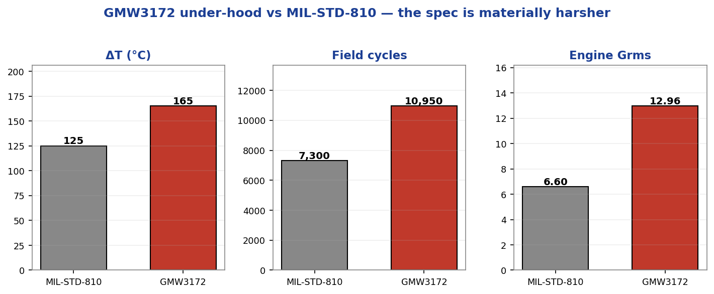
Here's the payoff of running the same engine twice. In our earlier demo, a board against MIL-STD-810 (−40/+85 °C) had its worst part — an 1812 polyfuse, the same part number this ECU carries — survive 2.86 years. Under GMW3172 code-H, Sherlock puts this board's 1812 polyfuse at 0.53 years: a 5.4× reduction across the two studies. Part of that is pure temperature: a closed-form Coffin-Manson calculation on the spec's own S-N slope says the GM swing drives about 2.1× more damage per cycle than the military swing. The rest is the board: the earlier study's board was a 68.58×53.34 mm two-layer standard-FR-4 Arduino-class build, against this 100×80 mm six-layer high-Tg 2 oz-copper ECU — a different laminate, stackup and copper mass around the same part number, and a sizeable factor in its own right. (Both studies cycle twice a day, so cycle count plays no part in the years ratio; the longer 15-year design life raises the end-of-life probability of failure but cannot shorten a part's years-to-failure.) The spec change and the board change compound, and we say so plainly.
The real-world connection
An engine control unit really is the brain of a modern car — it's reading sensors and firing injectors thousands of times a minute, and it has to keep doing it through a decade and a half of thermal abuse that would destroy a phone in weeks. The reason your car starts on a −30 °C morning and still runs after towing a trailer up a grade in August is that someone qualified that little box to a spec exactly like GMW3172. For a friendly tour of what's actually inside one and why it lives such a hard life, the ECU maker Haltech has a good primer:
The point of pushing this analysis left of the test lab is simple: a board that looks fine against one spec can fail another, and a physics-of-failure model tells you which parts, by how much, and why — months before you build a single prototype or book a thermal chamber.
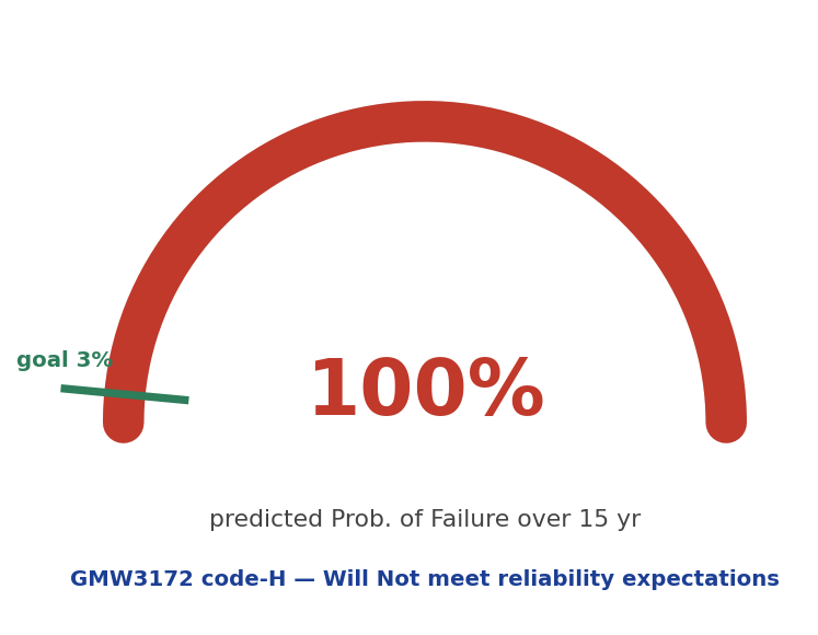
Qualifying an ECU or controller to an OEM spec like GMW3172 — and betting the program that a board which passed a milder profile will pass this one too? An SAE J3168-style reliability physics analysis in Ansys Sherlock — Solder Joint Fatigue and PTH Fatigue (IPC-TR-579) run against the GMW3172 code-H envelope, predicting a 100% probability of failure over the 15-year life against a 3% goal, cutting the 1812 polyfuse’s life 5.4× versus the same part number on our earlier MIL-STD-810 board, with the spec’s 1,348 test cycles kept strictly separate from Sherlock’s 10,950 field cycles so the acceleration factor is never counted twice — is how simulation names the failing parts, by how much and why, months before you build a prototype or book a thermal chamber. That's innovation through insight.