How Quenching Locks Stress Into Steel
Heat-treating steel almost always ends with a quench: heat the part until its crystal structure changes, then cool it fast enough to trap that structure and win hardness and strength. The cooling is the violent part. Drop a red-hot forging into oil and the outside meets the coolant first, contracting hard while the inside is still expanded and soft. The part cannot cool as one piece, and by the time it finally equalizes at room temperature it is carrying a self-balanced field of stress that no external load put there — residual stress. Get its sign right and you have armored the surface; get it wrong, or ignore it, and you have seeded a crack or warped a part past its tolerance. The only way to know which you have is to follow the temperature and the stress together, in time.
The surface and the core cool on different clocks
Whether a real gradient even forms is the first thing to check, and it comes down to a single number: the Biot number, the ratio of how fast the oil pulls heat off the surface to how fast the steel can conduct heat up from within. Here it is about 3.0 — taking h = 1500 W/m²K with the full 60 mm hub section as the characteristic length and hot-steel conductivity of about 30 W/m-K; the half-thickness convention would give roughly 1.5, and either convention lands far above the ~0.1 threshold where a part can be treated as cooling uniformly. The surface is being stripped of heat far faster than the thick hub can resupply it, so a steep through-thickness gradient is guaranteed, and it lasts: the hub's characteristic diffusion time is on the order of 447 seconds. The cut-away glow render above is that gradient made visible — a dark, already-cool skin wrapped around a core still hot enough to glow, seconds into a quench that takes minutes to finish in the middle.
Why the stress reverses — and ends up where it does
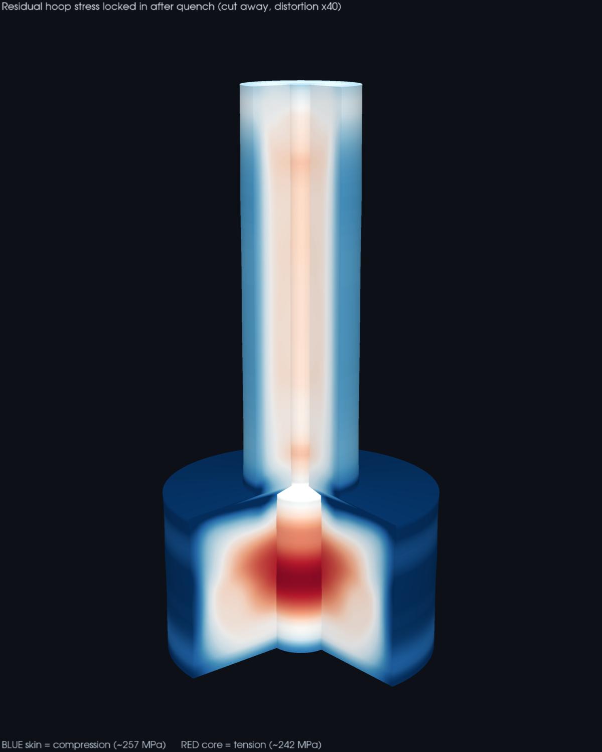
The mechanism is a two-act story, and it only works because hot steel is weak. As the surface cools first it tries to contract onto a core that is still hot, expanded, and soft. That puts the skin in tension — but at 850 C steel's yield strength is a small fraction of its room-temperature value, so the skin simply yields, stretching plastically to relieve the tension rather than building it up. So far the skin has been lengthened. Then the second act: the core finally cools and contracts in its turn, but now the skin is cold, hard, and permanently a little too long. The contracting core drags that stretched skin inward and puts it into compression — while the core, held out by the skin it is pulling on, is left in tension. The sign reversal is the whole point, and it hinges on the surface having yielded while it was hot. A model that used a single room-temperature yield strength gets this backwards; capturing it needs temperature-dependent, elastoplastic material data and the full cool-down solved step by step.
How big can it get? An absolute ceiling is the fully-constrained thermal stress, E·α·ΔT, which for this quench is about 1900 MPa — enormous, and far beyond what the steel can hold. That is exactly why the answer is governed by yielding, not by that bound: the metal reaches its (temperature- dependent) yield strength and plasticity caps the stress. The solved residual lands at 257 MPa of skin compression against a room-temperature yield near 350 MPa — a large fraction of yield, as residual stresses tend to be, but safely below it, which is the sanity check that the plasticity was handled right.
Skin in compression, core in tension
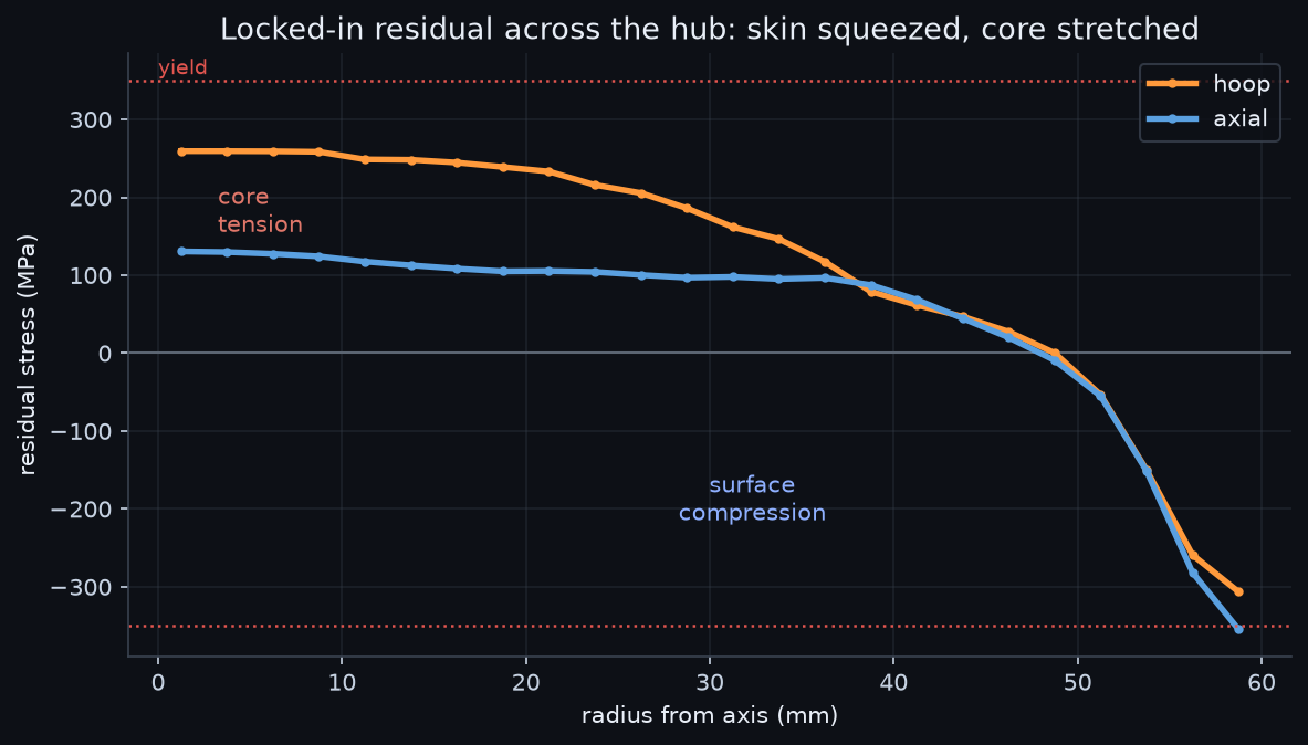
Read across the hub, the field is smooth and symmetric: a tensile core, a crossover partway out, and a compressive skin, in both the hoop and axial directions. This is the pattern metallurgists design around. The compressive skin is genuinely useful — surface compression is what makes shot-peened springs, quenched gears, and hardened shafts resist fatigue, because a crack cannot open against a surface that is being squeezed. The tensile core is the price: it is where a quench crack starts if the cooling is too aggressive, and together with the 0.57 mm of distortion it is why heat-treated parts are machined after quenching, with metal left on for exactly this movement. The thin shaft, which cools through quickly and evenly, carries far less of all of it — a reminder that section thickness drives the whole effect, which is why the hub–shaft step is the interesting part of this geometry.
Automation is the point
The forging was built and meshed once, and the whole chain — a transient thermal solve of the oil quench, then an elastoplastic structural solve marched through the same cooling history to accumulate the plastic strain that locks in the residual — ran unattended in Ansys Mechanical, checked against hand anchors at every step: the Biot number that guarantees the gradient, the E·α·ΔT bound that plasticity must cap, the surface-compression sign, and the self-equilibrium of the final field. Change the quench severity, the oil for water or air, the section thickness, or the steel, and the same script re-runs the story and returns the new residual magnitude, the new distortion, and whether the core tension is creeping toward crack territory. Turning “quenching stresses the part” into “257 MPa skin compression, 242 MPa core tension, 0.57 mm of distortion” is the everyday value of scripting the solver.
Part 2 — the same physics run backwards: a firebrick built to HOLD its heat
The quench above is a race to lose heat, and the punishment for winning is locked-in stress. Flip the goal and the same skin-versus-core physics becomes a feature: a thermal-storage firebrick is a block you heat glowing-hot precisely so it will give that heat back as slowly as possible. Same Ansys transient toolchain, same Biot-number story, opposite engineering victory condition — so we ran that study too, and it belongs in this post.
Thermal mass is how a pizza-oven floor, a night-storage heater, a re-entry tile backing, or a regenerator holds heat between when it is charged and when it is used. Two questions decide whether the design works: how fast does the stored heat leak away, and how evenly is it held inside the block? Both are transient, both are set by the interplay of conduction inside the solid and radiation-plus-convection at its surface, and both are easy to get wrong with a back-of-envelope estimate.
The estimate people reach for is the lumped model — treat the whole block as one temperature and let it decay exponentially. It is quick, and for this brick it is quietly wrong. The test is the Biot number, the ratio of internal conduction resistance to surface loss resistance; below about 0.1 the block is effectively isothermal and the lumped model holds. This firebrick comes out around 1.9. Conduction through low-conductivity refractory is the bottleneck, not the surface loss, so the block cannot stay uniform — and the only way to see what it actually does is to solve the temperature field in time.
There is a second reason the surface cools so fast that the animation makes obvious: while the brick is hot, it loses heat mostly by radiation, not by the still air around it. Radiation scales as the fourth power of absolute temperature, so at 799 C a bare surface throws off several times more heat by glowing than by warming the air — which is exactly why the surface can shed hundreds of degrees in minutes. As it cools that radiative term collapses (the fourth-power curve falls away steeply), the two loss paths become comparable, and the cool-down slows of its own accord. A model that lumps the surface loss into a single constant coefficient misses this entirely; the mixed radiation-plus-convection boundary in the solve captures it, which is part of why the solved surface curve bends the way it does.
Why a firebrick is not one temperature
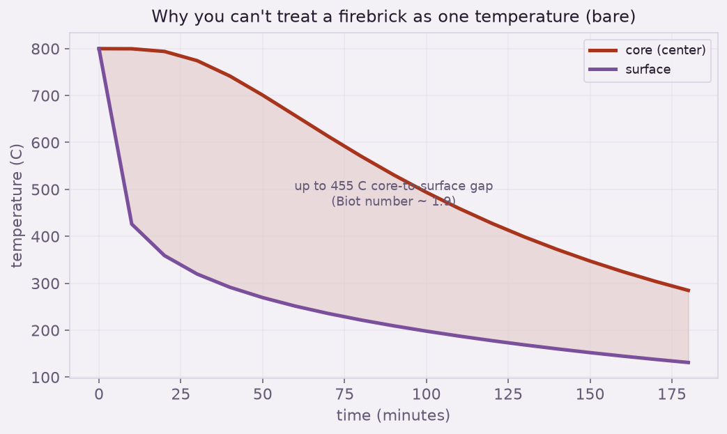
That gap is not a curiosity; it is the design. If you size a heat store on a lumped average you will overestimate how much you can draw quickly (the surface is already cool) and underestimate how long the core stays dangerous or useful. The transient field is what tells you both. It is also what the glow animation shows literally: the dark shell and the glowing heart are the same solve, seen as light.
What insulation buys
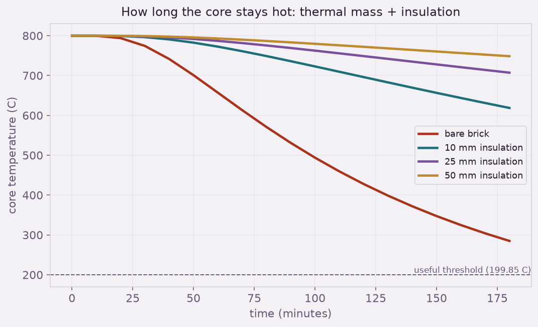
The insulation acts where the heat finally leaves — the outer surface — by adding a conduction resistance in series with the convection and radiation. A few tens of millimeters of mineral wool swamp the surface film, and because the loss is now limited by the wrap rather than the brick, the lumped model becomes valid again (the Biot number drops below 0.1) — so the retention past the solved window can be read off with confidence.
The same two clocks — a fast surface and a slow core — run in a lot of everyday hardware. A pizza or bread oven's stone floor is charged for an hour so it can dump heat into dough in ninety seconds: that only works because the stone holds a hot core the surface can draw on. A night-storage heater banks cheap off-peak heat in a refractory core and bleeds it out through the day. A regenerator in a furnace or a Stirling engine cycles heat in and out of a solid matrix on every stroke. In each case the design question is the one solved here: how deep does the heat sit, and how fast can it reach the surface where it is used or lost? Get the thermal mass and the insulation right and the device runs on the schedule you need; size it on a lumped average and it is either cold when you reach for it or still dangerous when you think it has cooled.
Automation is the point
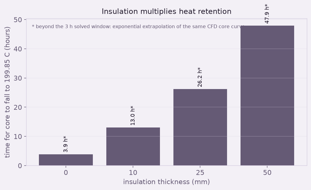
One brick was meshed once, and a script swept the insulation as a surface resistance and ran each cooling transient in Fluent unattended, snapshot by snapshot, checked against the lumped-capacitance law wherever that law is valid. The output is a retention chart an engineer can size a heat store from — and a check, from the Biot number, on when the easy estimate can be trusted and when it cannot. Turning “insulation helps” into “50 mm buys you 12x the hold time” is the everyday value of scripting the solver — and the same loop would extend without fuss to a different refractory, a larger block, or a duty cycle that charges and discharges the store over and over.
Heat-treating, quenching, welding, or shrink-fitting a part where the process leaves stress behind? Residual stress decides whether a surface resists fatigue or cracks in service, and whether a part holds its tolerance — and it is a coupled, history-dependent solve, not a single number. We do transient thermal and elastoplastic residual-stress work in Ansys Mechanical. Rand Simulation — innovation through insight.