Resources · Solutions Blog · Fluids / Wind Loading
Will the Swing Set Survive the Storm? CFD Wind Loads on a Backyard Playset
RS
Rand Simulation — Applications Engineering AI External aerodynamics · Ansys Fluent · PyFluent (fully headless) · 7 min read
AI disclosure: RandSim Labs is an experimental AI-driven engineering simulation platform. Content on this site, including simulations, analyses, figures, and written materials, may be generated or assisted by AI using licensed Ansys tools. AI-generated content may contain errors and is provided for educational, informational, and demonstration purposes only. Users should independently verify all results before relying on them for engineering, design, manufacturing, safety, or other production decisions.
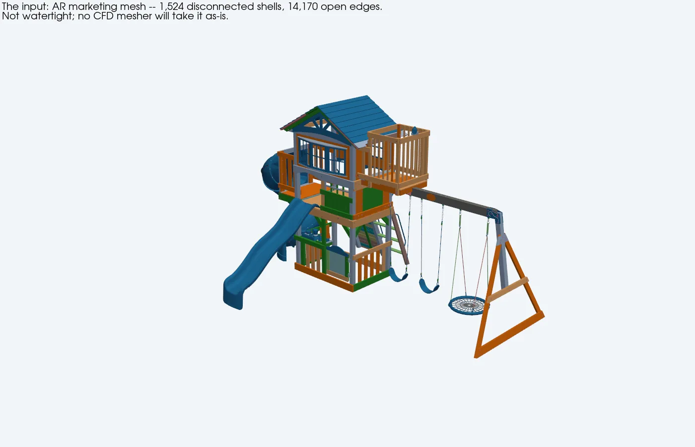
A 620-pound cedar playset is a kite with a clubhouse. Every spring, somebody's swing set ends up in the neighbor's yard — and the manufacturer's fix is a bag of seven unrated corkscrew stakes. So we did what we'd do for any structure: put the actual geometry in a wind tunnel. A digital one. The twist: the only geometry available was the retailer's AR marketing model — 1,524 disconnected shells that no mesher will touch — and the goal was a number you can bolt to the ground: how many earth anchors, what size, and where.
1 · The geometry problem (and the shrink-wrap fix)
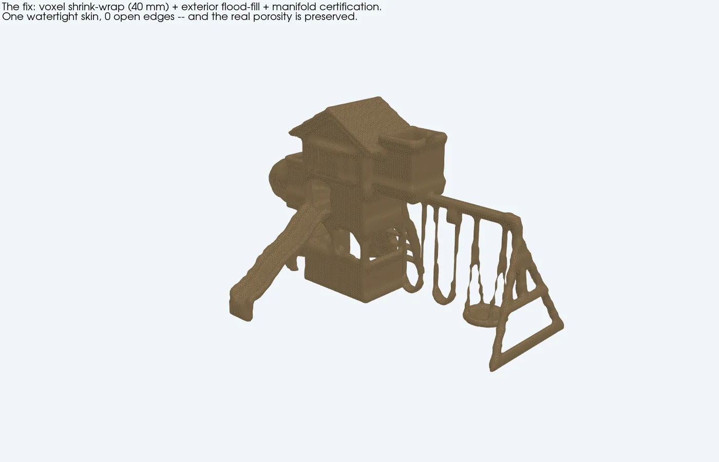
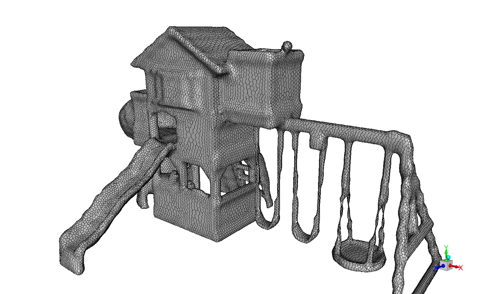
Top: the input — an AR visual mesh where every board is its own open shell (each color is a disconnected piece). Bottom: the fix — a voxel shrink-wrap (40 mm occupancy field + exterior flood-fill + marching cubes, with an automated manifold-certification loop). One watertight skin, zero open edges — and, crucially, the porosity survives: the solid frontal area is 8.9 m², not the 21 m² of the bounding envelope. For an open-frame structure, that porosity is the aerodynamics.
You could rebuild the playset as clean CAD prisms — but then the drag area is whatever you assumed when you drew it. Wrapping the real mesh keeps the actual openness of the frame, so the CFD produces an independent drag area instead of echoing your sketch. Thin members (swing chains, rails) thicken to ~6 cm in the wrap — a small conservatism in the right direction.
2 · What we ran
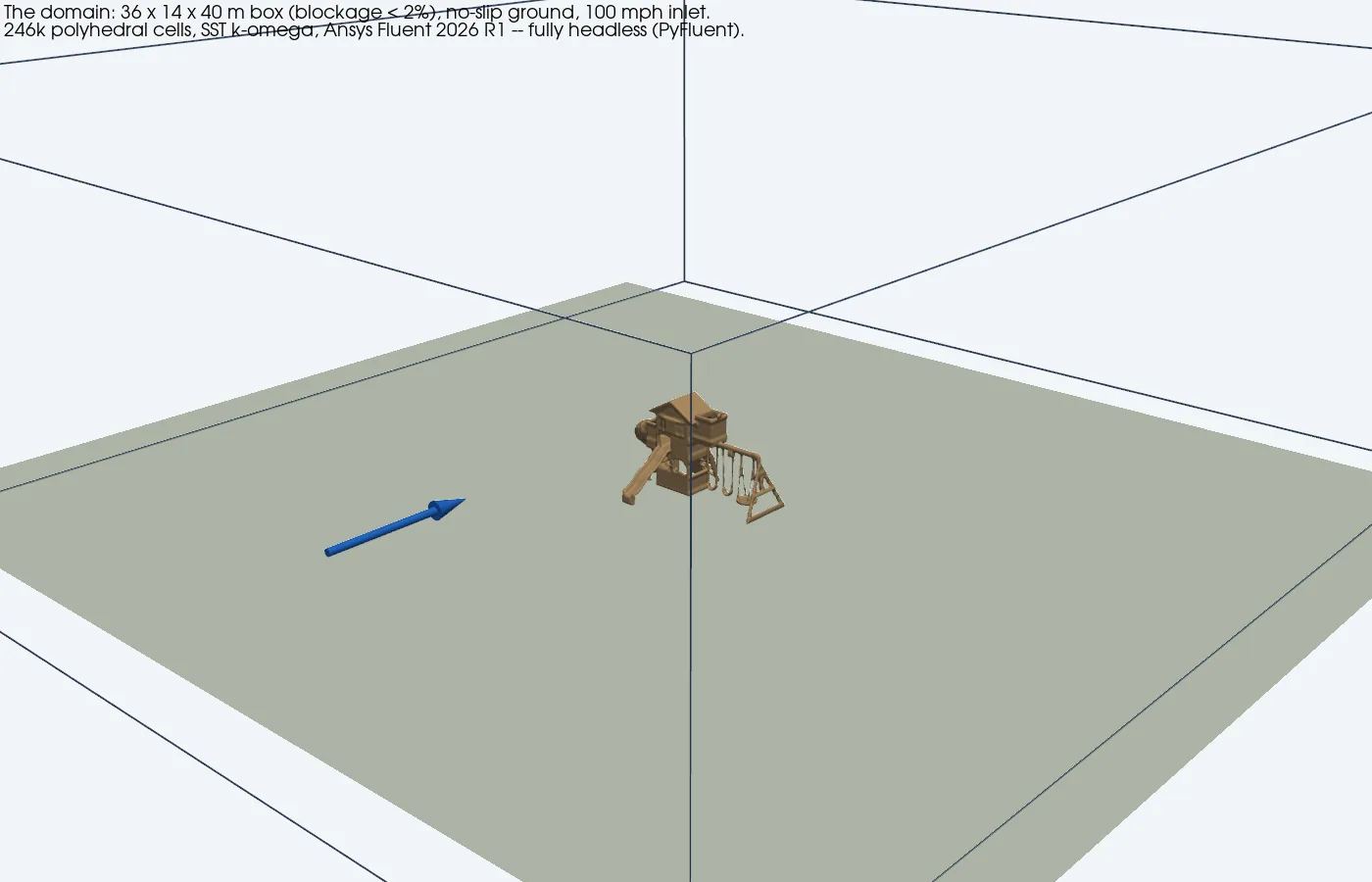
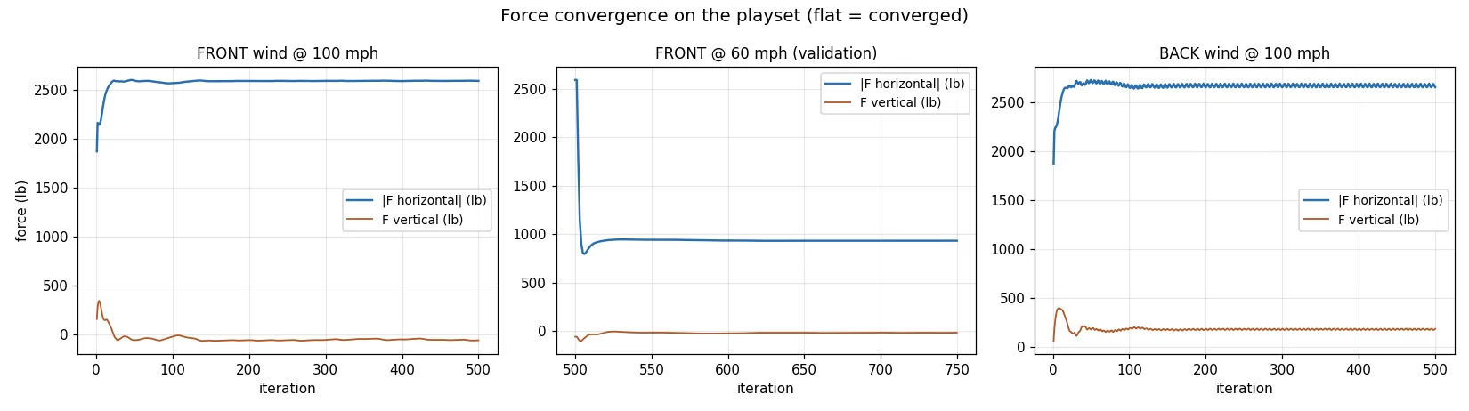
The actual solve: a 36×14×40 m domain (blockage <2%), no-slip ground, 246k polyhedral cells, SST k-ω, steady RANS at a uniform 100 mph — Ansys Fluent 2026 R1 driven end-to-end by script (PyFluent), no GUI ever opened. Three runs: wind on the front (slides face), wind on the back (rock-wall face), and a 60 mph validation point.Force convergence for all three runs — flat tails, with the small ripple you expect from steady RANS on a bluff body (we report the converged mean).
3 · What the wind actually does
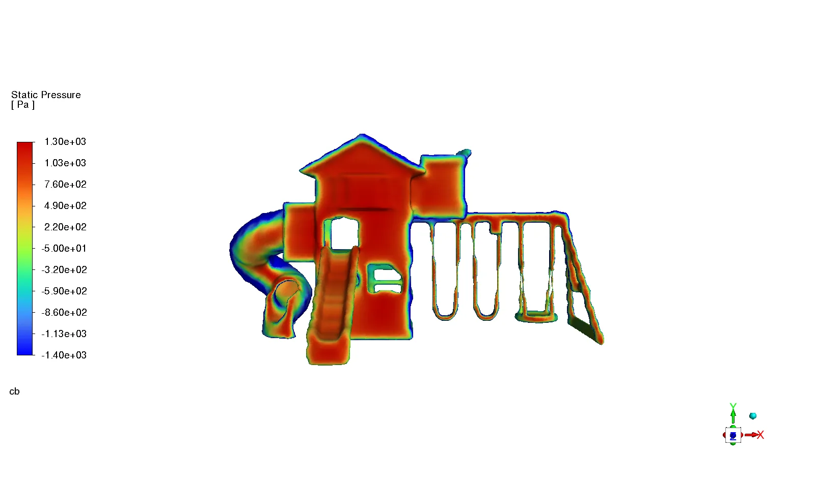
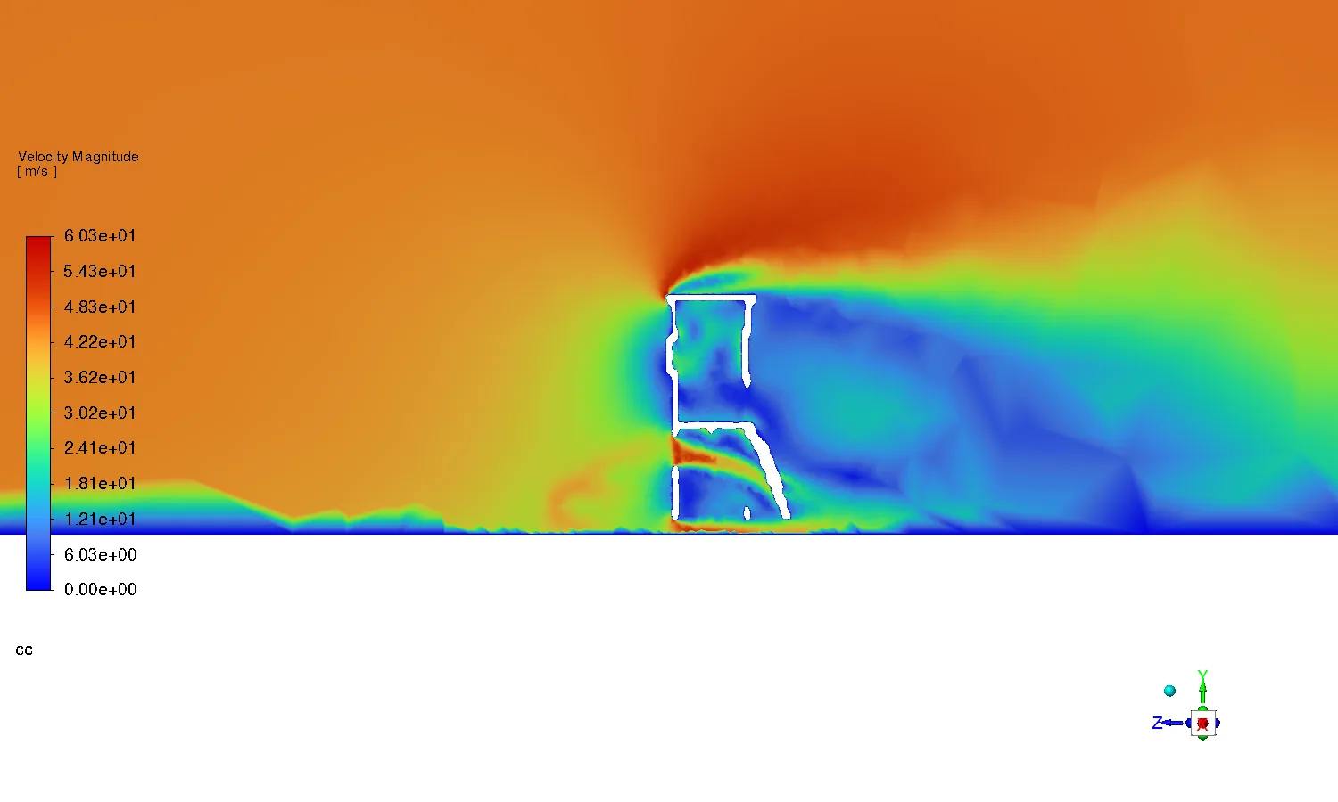
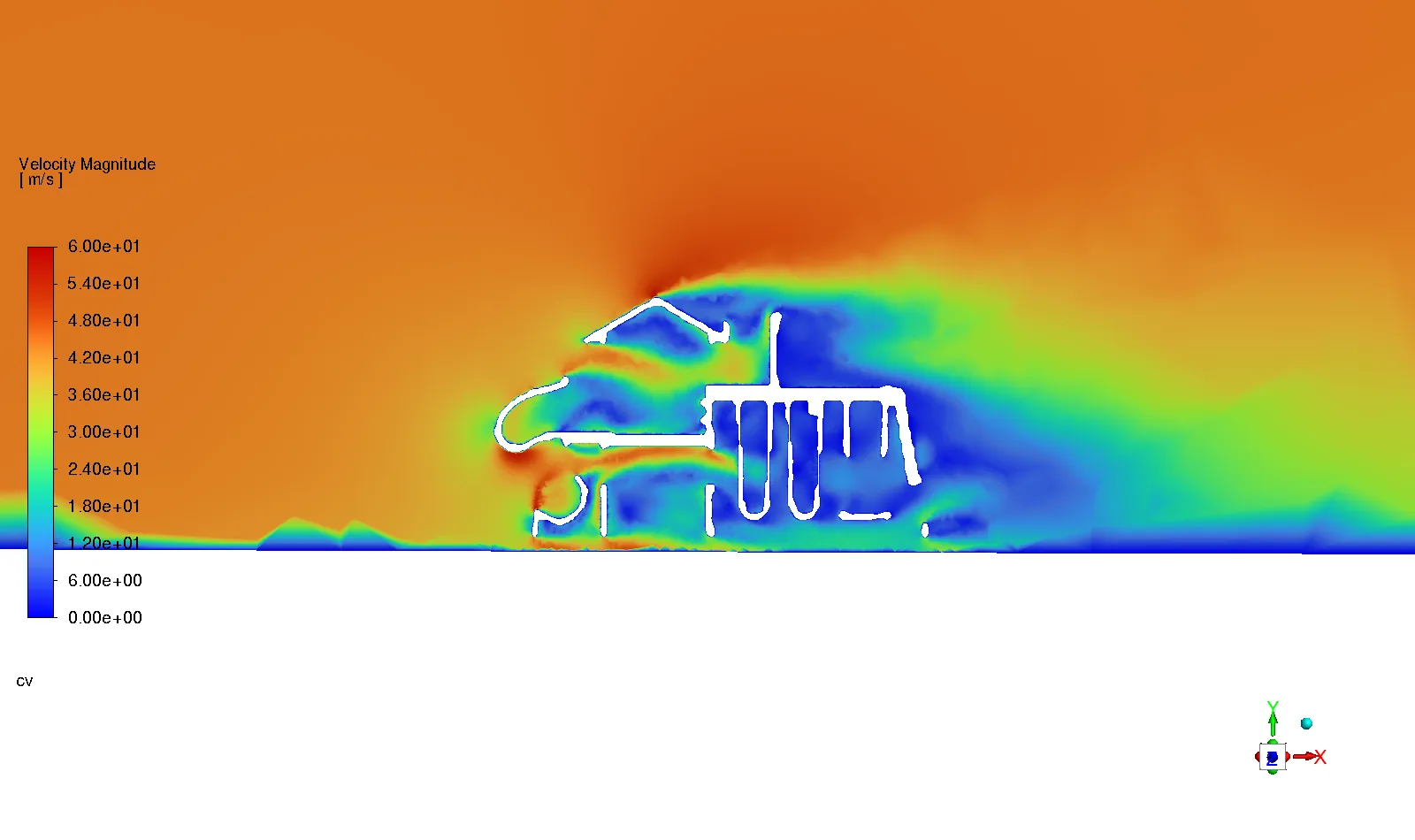
Surface pressure at 100 mph, front wind (fixed color range). Red = stagnation pressure driving the set over; blue/green = suction wrapping the slide flanks and roof edges.“Pressure on the front” — literally. The windward face carries ~+1.0–1.3 kPa (right at the 1.22 kPa dynamic pressure of a 100 mph gust), and you can see which parts of the structure do the work: the clubhouse and tower are the sail; the swing bay is nearly transparent.Velocity through a vertical plane: flow accelerates to ~55+ m/s over the clubhouse roof, jets under the deck, and leaves a wake several set-lengths long. That pressure difference across the structure is the overturning couple.A velocity slice sweeping down the length of the set: the flow threads clean through the open swing frame, then hits the wall of the clubhouse.
4 · The numbers — and a validation that earned its keep
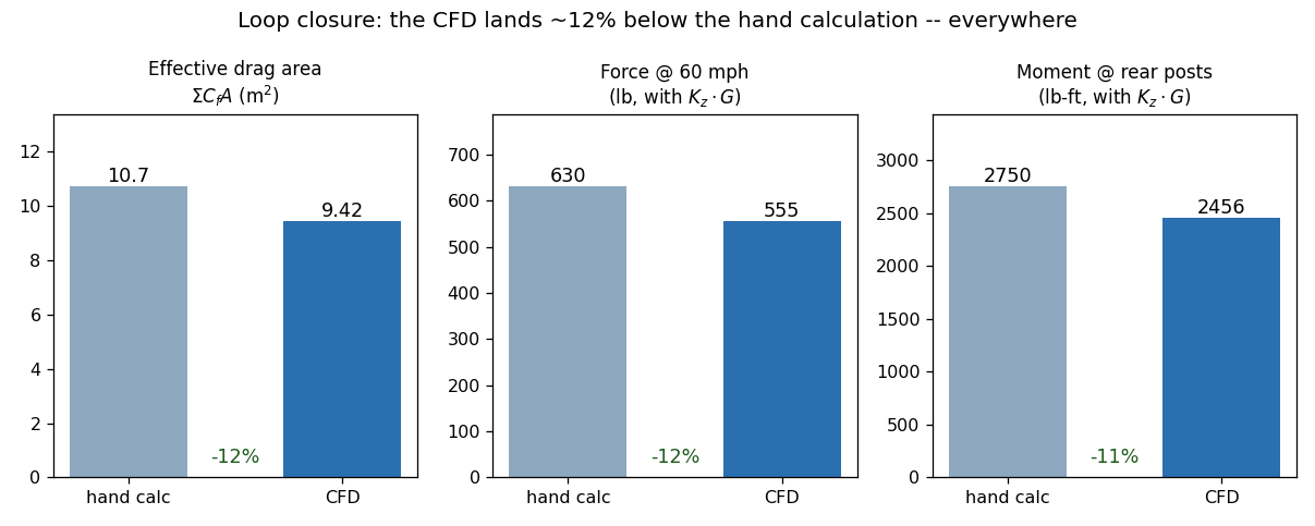
Before running the CFD we did what any engineer should: a hand calculation. Component-by-component projected areas off photos, drag coefficients from the literature, ASCE-7-style Kz and gust factors. Its entire aerodynamic content collapses to one number — an effective drag area of 10.7 m² — carrying an honest “±30%, my areas are photo-estimates” caveat. The CFD was run specifically to test it.
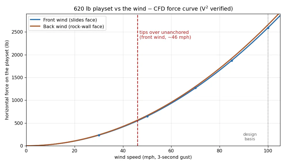
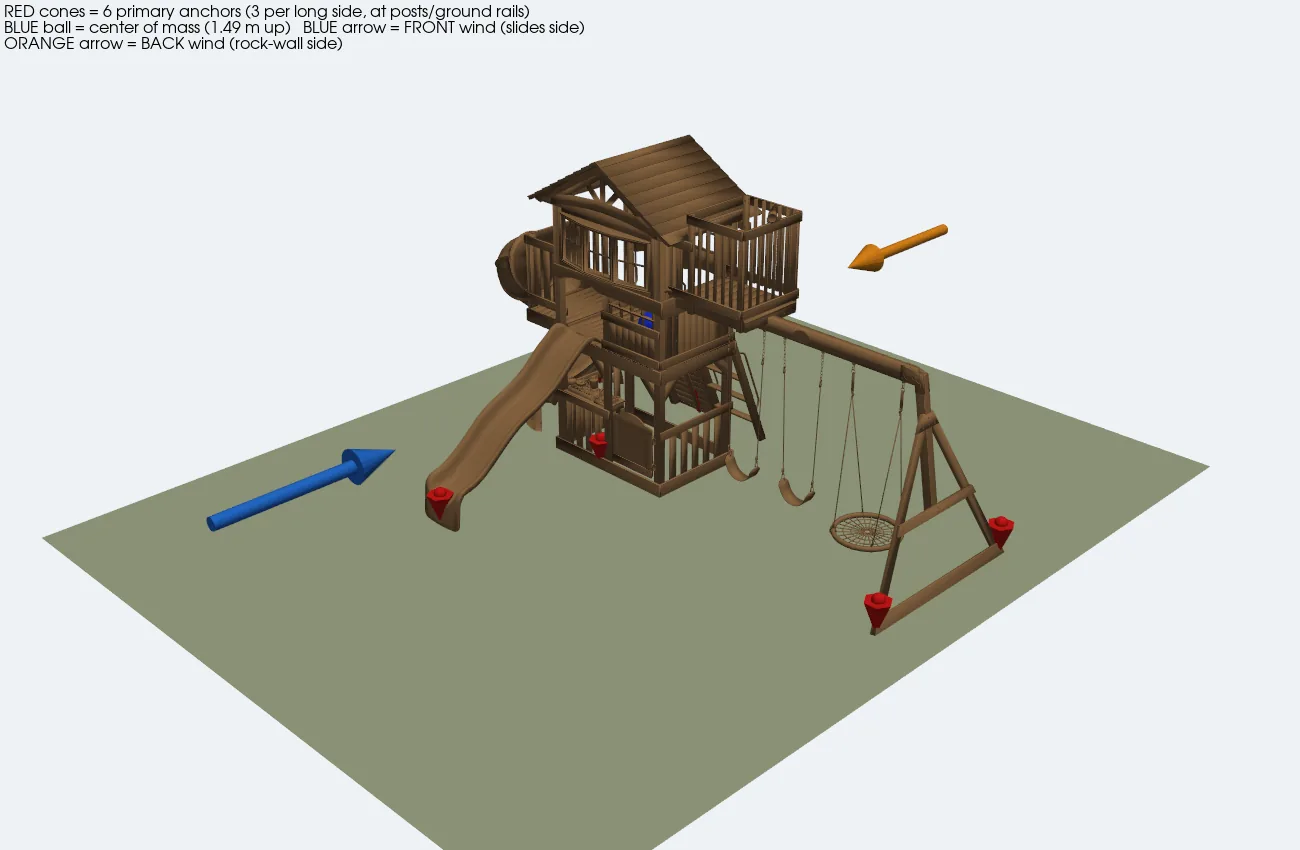
The loop closes: on the front (slides) face, CFD lands ~12% below the hand calc on drag area, force, and overturning moment alike (the back, rock-wall face comes in ~9% below). The hand calc was conservative — but only mildly. Neither model now rests on guessed areas.The design curve. At 100 mph the wind pushes with ~2,600 lb — more than four times the playset’s weight. Unanchored, it tips over at about 46 mph, in the direction you’d least expect: wind on the slides face, rotating backward over the rock-wall posts, because the center of mass (1.49 m up) sits toward that side.
5 · Then we spun the wind around: all six directions
Front and back answer the design question, but wind doesn’t read manuals — so we re-ran the same model with the wind end-on from both ends and quartering at 45° onto both corners (for the oblique cases, two adjacent domain faces become velocity inlets carrying the diagonal vector). Six converged solutions, one polar plot:
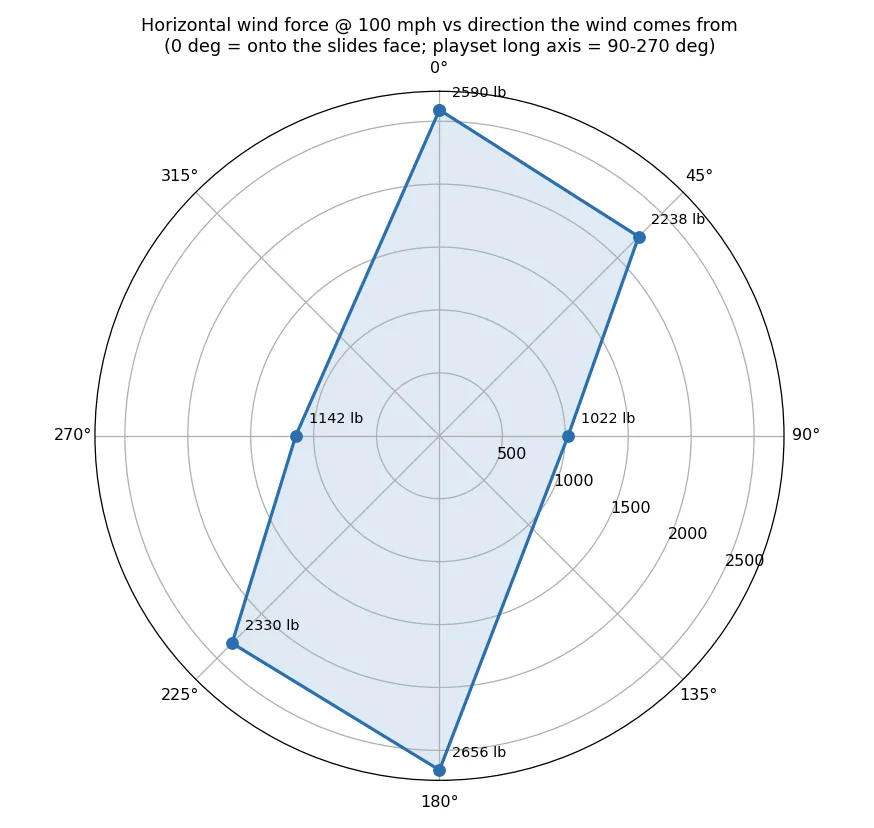
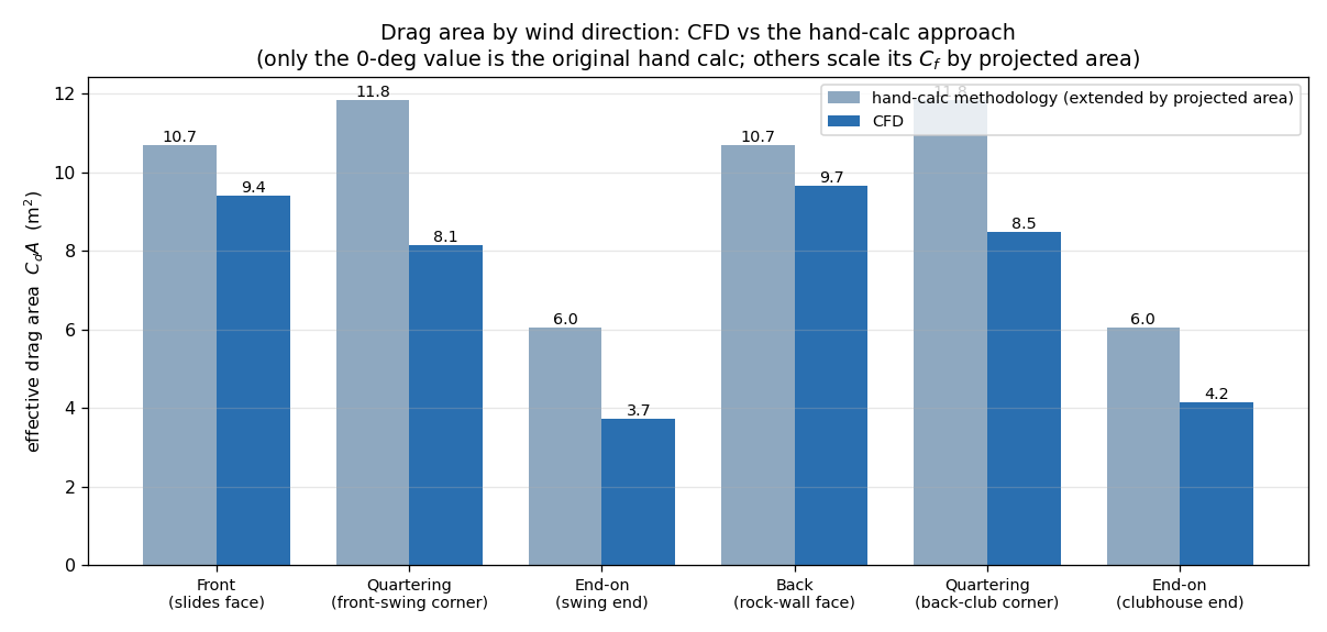
The force lobe at 100 mph. Broadside dominates (~2,600 lb); the 45° quartering winds carry almost as much total force (~2,300 lb) but split it across both axes; end-on the 6-m-long frame is nearly transparent (~1,100 lb).Quartering wind, surface pressure: stagnation striping down both windward faces at once. For buildings this is often the governing case — here it isn’t: the split components see longer restoring arms, so its anchor demand is about half the broadside case.Why end-on is easy: velocity down the long axis shows each member sheltering the next — the drag area collapses to ~4 m², and with a 6 m footprint to lever against, the set won’t tip end-over until a (theoretical) 112+ mph.The hand-calc comparison, extended to every direction by projected area: the CFD comes in below it everywhere — 9–12% broadside (12% front, 9% back), ~30% quartering, ~35% end-on, growing exactly where member-shielding (which a component buildup can’t see) grows. The hand method is a safe upper bound in all directions; the CFD tells you by how much.
Wind direction
Fh @ 100 mph
CFD CdA
hand-calc (ext.)
windward-row anchor demand (SF 2.0)
unanchored tip-over
Front (slides face)
2,591 lb
9.4 m²
10.7 m²
1,745 lb
46 mph
Back (rock wall)
2,656 lb
9.7 m²
10.7 m²
1,891 lb
60 mph
Quartering (2 corners)
2,238–2,331 lb
8.1–8.5 m²
11.8 m²
915–1,023 lb
58–79 mph
End-on (2 ends)
1,022–1,142 lb
3.7–4.2 m²
6.0 m²
0–125 lb
112–249 mph
The verdict holds: broadside wind on the long faces governs everything — the six-anchor layout sized for it covers every other direction with margin to spare. (One screening caveat: our quartering tip-over check works the two principal edges separately; a true corner-pivot check would land between them, still far from governing.)
6 · The deliverable: anchors, sized and placed
Six primary earth anchors (red), three per long side, at the corner tower posts and swing A-frame legs; blue marker = center of mass. With a safety factor of 2.0 at 100 mph, each windward row must hold ~1,900 lb — three 36″ screw-in anchors (~2,100 lb ultimate each in medium soil) give 3× that. The seven corkscrew stakes in the box? ~350–600 lb each: fine for keeping the set from walking, not for a 100 mph design gust.
One more design move fell straight out of the moment balance: extending short “feet” ~0.6 m beyond the rock wall — the weak tipping edge — raises the unanchored tip-over speed from 46 to ~56 mph and cuts the anchor demand ~20%. Cheap wood, real margin, and the anchor at the end of each foot gets the best lever arm on the property.
What actually makes this work
Porosity is the aerodynamics. The envelope says 21 m² of frontal area; the real, open structure presents 8.9 m² solid and an effective drag area of 9.4 m². Any method that seals the gaps — a coarse CAD remodel, an over-aggressive wrap — overpredicts the load and buries the actual engineering question.
A hand calc plus a targeted CFD beats either alone. The hand calc frames the problem and catches blunders; one cheap validation run (the 60 mph point warm-started from the 100 mph field) converts “±30% maybe” into “about 12% conservative” — cross-checked against the hand calc, though on a single screening mesh rather than a grid-independence study.
Headless means repeatable. Geometry wrap, domain, mesh, three solves, force extraction, tie-down math, every figure and animation on this page: scripts. Change the drop… er, the wind speed, the soil class, or the playset model, and the whole study re-runs.
Revisions
v2 · Internal reviewScoped the 12%-below-hand-calc claim to the front face (back face ~9%) and disclosed that the single 246k-cell mesh carried no grid-independence study; forces unchanged.
Honest scope. This is a screening study, not a stamped design: steady RANS on a shrink-wrapped model (geometry effects we estimate at ±10–15% on force), a uniform inlet (no boundary-layer profile — conservative at playset height), a uniform-density center-of-mass proxy, and generic “medium soil” anchor ratings — real capacity varies strongly with moisture, so proof-pull an anchor if it matters. The runs used a single 246k-cell mesh with no formal grid-independence study, so the drag areas carry a mesh-discretization uncertainty on top of the geometry effects above. The 100 mph 3-second gust is an inland ASCE-7-style basis; check your county’s map. And the usual manufactured-housing convention applies: certified anchors are rated at working load = ultimate/1.5; we used SF 2.0 on field-tested domestic anchors.
Is there an open-frame structure on your site — a canopy, a sign, a shade frame — held down by anchors nobody ever sized? Ansys Fluent 2026 R1, driven end-to-end by PyFluent with no GUI ever opened — steady RANS at 100 mph swept through six wind directions, forces read off converged flat tails, and the whole study held against an independent hand calculation it came in ~12% under on the governing broadside case (more on the oblique ones) — is how simulation turns “probably fine” into a bolt-down answer of six earth anchors at ~1,900 lb per windward row, before the next spring storm runs the experiment on your property. That's innovation through insight.
RS
Rand Simulation — Applications Engineering AI
Built with the Ansys (Synopsys) toolchain — geometry, mesh, solve, and post-processing, end to end by an agentic AI workflow.