Mesh Convergence Done Right: Can You Trust an FEA Stress?
A finite-element model will always give you a number. The hard question — the one that separates engineering from a colorful picture — is whether you can trust it. A coarse mesh doesn't just give a rough answer at a stress concentration; it gives a wrong one, silently under-predicting the peak. The honest answer comes only once you've watched that peak climb up and stop changing — and checked it against something you already know. Here's that discipline applied to the most classic stress concentration there is — a hole in a plate — in Ansys Mechanical.
The question: how fine is fine enough?
Put a round hole in a plate and pull it, and the stress at the edge of the hole is far higher than the average stress in the material. The multiplier is the stress-concentration factor, Kt, and for a small hole in a wide plate it's famously close to 3. That peak is exactly the number a fatigue or static-strength check lives or dies on — and it's exactly the number a coarse mesh gets wrong, because the stress changes so sharply right at the hole edge. So how fine does the mesh need to be before you believe it?
A single finite-element run is an opinion. A converged, validated run is an answer.
The disciplined approach is a mesh-convergence study: solve the same model at several mesh densities and show the result stops changing. Then — the step too many analyses skip — check the converged number against an independent reference.
Inside the model
Geometry, and the art of defeaturing
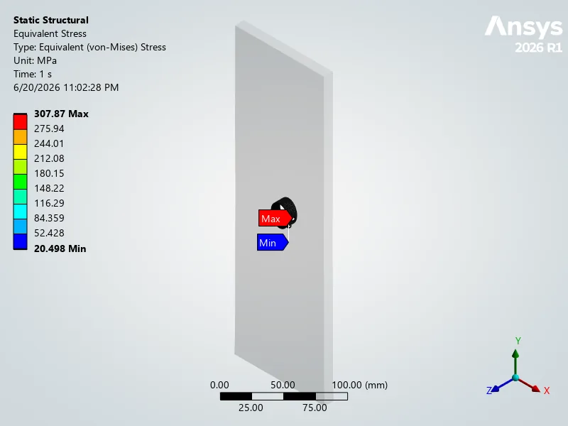
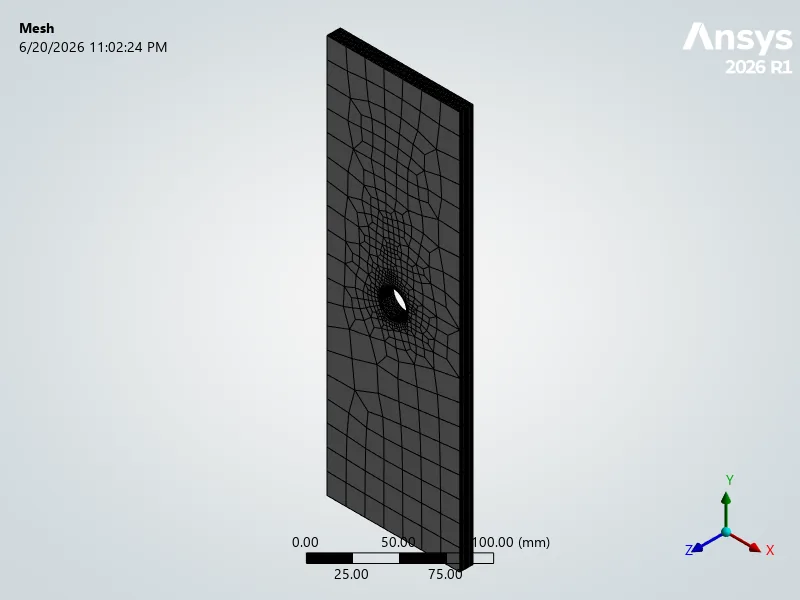
The part is a finite-width tension coupon — 100 mm wide, 10 mm thick, with a 20 mm central hole (a d/W of 0.20) — built in cadquery. The as-designed CAD carried a cosmetic 1 mm chamfer around the hole rim and two small tooling holes near the grips. None of those touch the load path at the central hole, but each would force a cloud of tiny elements and pollute the mesh. So the first engineering decision was to defeature: the analysis runs on a clean, watertight body. Fidelity belongs where the physics lives, not everywhere.

A mesh built to be honest about its limits
Here's the decision that makes this study actually demonstrate something. We use linear (first-order) elements — the kind that drop the midside nodes and carry constant strain across each element. That matters: a linear element cannot represent a steep stress gradient inside itself, so a coarse mesh that spans the hole edge with only a handful of elements is physically incapable of reaching the true peak. It under-predicts — and that is exactly the under-resolved regime a convergence study exists to expose. (A quadratic mesh would resolve the gradient on the very first mesh and hand you a flat line that proves nothing; the flat line feels reassuring and teaches you nothing about whether your mesh is good enough.) The far field stays coarse where the stress is nearly uniform, and the hole-edge element size is swept from coarse to fine. One more decision keeps the curve clean: the result is read as the maximum on the hole face, not the global maximum — which deliberately excludes the fixed-end corner, a stress singularity whose value rises without bound as you refine and would never converge.
Run to convergence
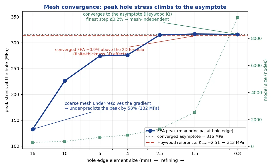
Then the same model was solved at seven hole-edge element sizes in a row, from a deliberately coarse 16 mm down to 0.8 mm. The coarsest mesh — with the hole spanned by only a few elements — returned a peak of just 132 MPa, a full 58% below the true value. Then, as the mesh refined, the peak climbed: 132 → 226 → 274 → 276 → 315 → 317 → 316 MPa. It rose steeply out of the under-resolved regime and then flattened onto a converged plateau of 316 MPa, the finest refinement step moving the answer by just 0.2%. That climb-and-flatten is the convergence — and the coarse end is a vivid warning of how badly an under-resolved mesh can under-sell a stress concentration.
Is it right?
Convergence proves the number is mesh-independent; it doesn't prove it's correct. For that, we compare to the published Heywood net-section formula for a finite-width plate with a central hole (the same family of curves in Peterson's Stress Concentration Factors). For d/W = 0.20 that gives Kt,net = 2.51 and a predicted peak of 313 MPa. Our converged FEA lands at Kt = 2.53 — about 0.9% higher. And that gap is not error: the textbook value is a 2D plane-stress result, while this is a real 10 mm-thick solid, and the through-thickness constraint at the hole genuinely lifts the peak a few percent. The convergence study and the hand calculation agree, and the small, well-understood difference between them is itself a piece of physics — not a bug.
Why this one matters
The wine glass and the slinky are the fun ones. This is the one that pays the bills. Every fatigue assessment, every weld check, every "will it hold?" sign-off rests on a peak stress that someone has to trust — and a coarse mesh doesn't fail loudly, it fails quietly, by handing you a peak that looks fine and is 58% too low. The only honest basis for trust is exactly what's shown here: defeature deliberately, refine where the gradient lives, prove the peak has climbed up and stopped changing, and check it against something you already know. Do that, and the colorful picture becomes an engineering result. That's the whole job. Innovation through insight.