Firing on the Whole Assembly: A 9-Part Slider-Crank Under Load
RS Rand Simulation · Applications Engineering AI · June 2026 · 11 min read
A single part, analyzed in isolation with clean boundary conditions, is the easy case. Real machinery is
an assembly — parts that touch, slide, bolt together, and hand load to one another — and the
interesting stresses live exactly at those handoffs. We took a nine-part slider-crank mechanism — piston, wrist
pin, connecting rod, cap, bolts, bearings, crankshaft — and put the whole thing through a multi-step static
structural analysis in Ansys Mechanical, the way the load actually arrives during a firing stroke.
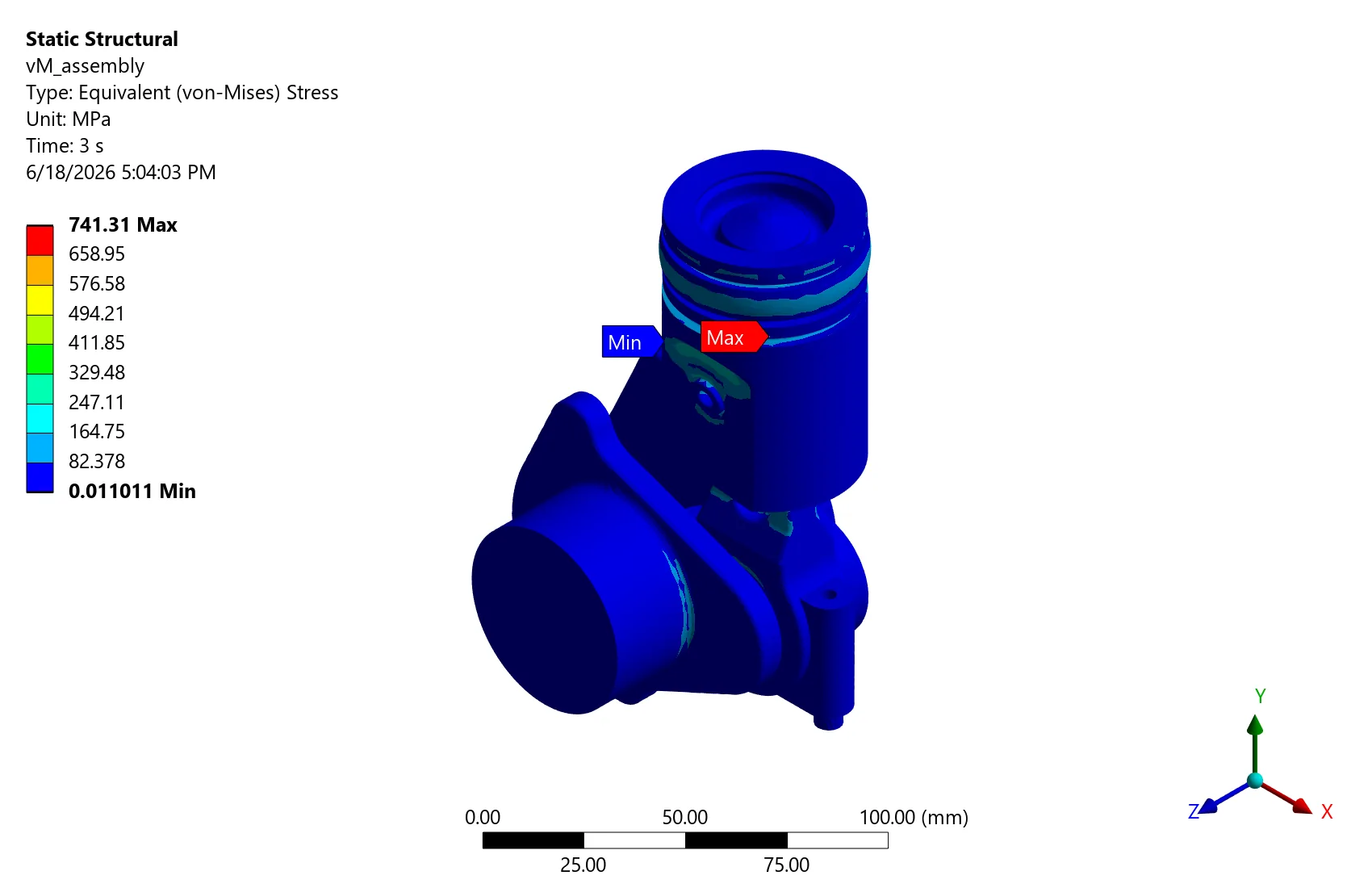
Von Mises stress on the assembled slider-crank under combined load. The peaks concentrate at the contact
interfaces — the wrist pin and rod small-end — exactly where an isolated single-part model would miss
them.The load arriving, step by step. This is the actual multi-step static solve played back from the result
file (no re-run): von Mises on the deformed nine-part assembly through the three load
steps — gravity (the assembly just settles, field near zero), + bolt preload (the bulk field
climbs to a few hundred MPa as the cap bolts clamp), then + gas pressure (the firing load drives in and the
bulk reaches ~470 MPa, with the genuine peak of 741 MPa concentrating at the wrist-pin contact). Displacement
is the real solved field warped ×60 for visibility (peak motion is only ~0.29 mm); the undeformed assembly
is ghosted. Color scale is capped at the per-body assembly peak so the build-up reads cleanly — the same honest
cap as the still figures below.
Load that arrives in steps
The analysis is built as a sequence, because the loads don't all show up at once. Step 1 settles the assembly
under gravity. Step 2 applies the bolt preload that clamps the rod cap. Step 3 brings the gas pressure of the
firing stroke down onto the piston crown. Frictional contact at the sliding and bolted interfaces carries the load from
one body to the next, so the final stress state is the genuine assembly response — preload and gas load acting
together through real contact — not a superposition of tidy single-part runs.
The hard part was the geometry, not the physics
Assemblies imported from real CAD are rarely watertight: faces don't quite touch, bodies interpenetrate slightly,
and the contact detector either misses pairs or jams. Getting this one to solve cleanly took a documented recipe —
per-body meshing with cross-body corner node-welds to stitch the dirty interfaces, and a piston-skirt bore-guidance
constraint that removes a rigid-body swing mode in the connecting rod that would otherwise stop the solver cold. Those
fixes are the difference between “the model won't converge” and a result you can read.
The result: the assembly peaks at about 741 MPa von Mises at the wrist pin —
the most heavily loaded contact in the mechanism — with the connecting rod (~487 MPa) and piston
(~477 MPa) next, and the crankshaft comfortably lower (~127 MPa). A companion modal and linear-buckling pass
rounds out the picture — both shown below — and a Goodman fatigue post-process turns the stress field into
per-part safety factors.
What the assembly result actually contains
The single contour above is the headline, but it is a fraction of what the solved model holds. The result file
carries the full stress and displacement field at every one of the three load steps, plus a companion modal and
linear-buckling pass — all from the same solved assembly. Below we mine it. Everything here is
post-processed from the existing solve (no re-run): the per-body stress peaks come straight from Ansys Mechanical's
evaluator, and the section, displacement, mode-shape and buckling figures are rendered from the same solved result
file.
Cut it open: the 741 MPa lives inside the bore
The whole thesis of running an assembly is that the dangerous stress hides at a contact interface that an isolated
part-model never sees. The cleanest way to prove it is to slice the model open. We pass a cutting plane through the
wrist-pin axis and look at von Mises on the exposed interior — the through-thickness stress in the pin and the
rod small-end bore that no surface plot can show.
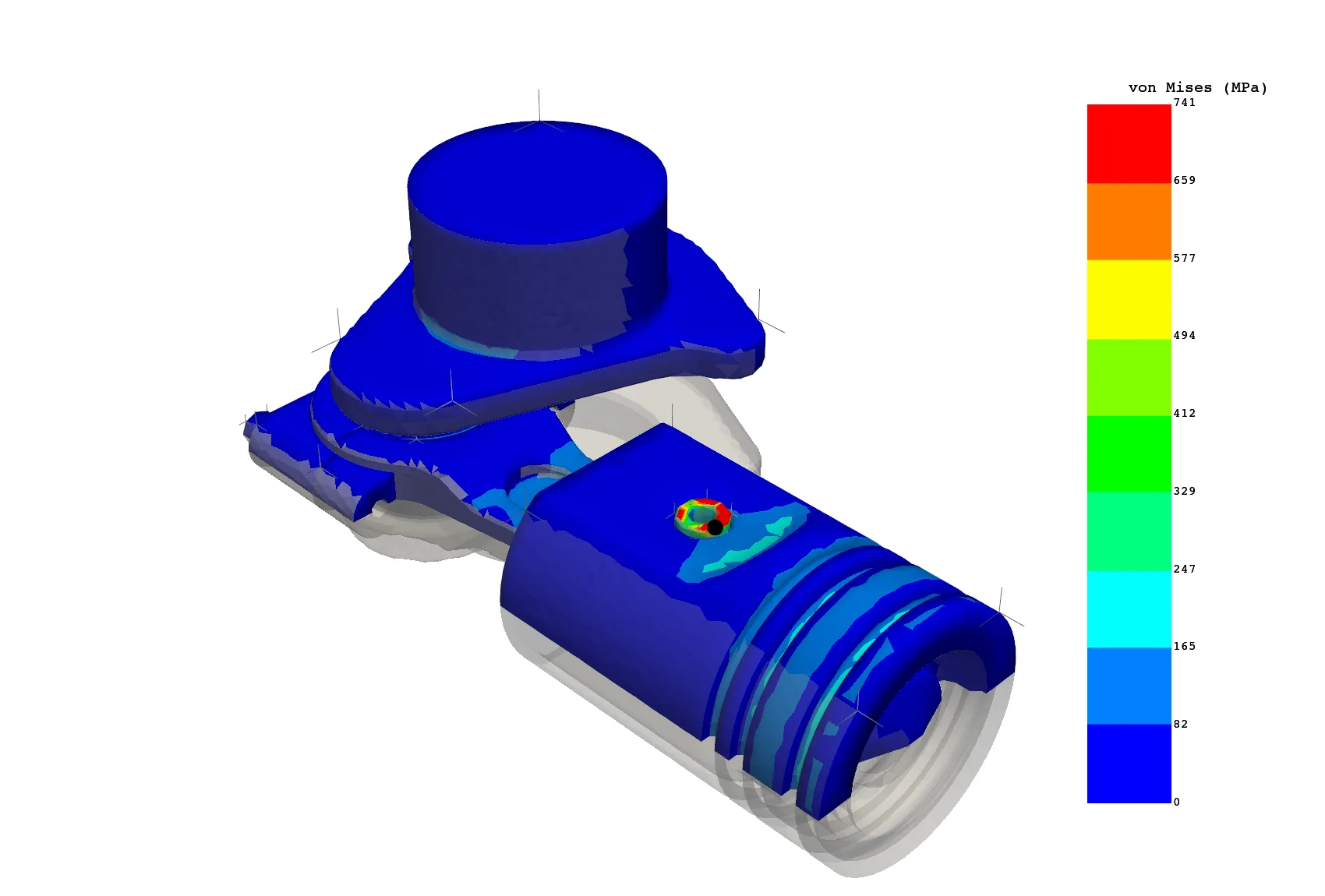
Section cut through the wrist-pin and connecting-rod small-end, von Mises stress on the interior.
The hot spot sits on the inside of the bore where the pin bears against the rod — the
741 MPa peak the headline number refers to. The surrounding bodies are ghosted; the contour scale is
capped at the per-body assembly peak so the band plot reads cleanly. This is the single best demonstration of
“extract the internal stress”: the worst stress in the whole machine is on a surface you can only see by
cutting the part in half.
Watch the load arrive: stress redistributing over three steps
Because the analysis is staged, we can watch the stress build as each load lands. The three frames below are the end
of each load step on a shared color scale, so the redistribution is honest and comparable.
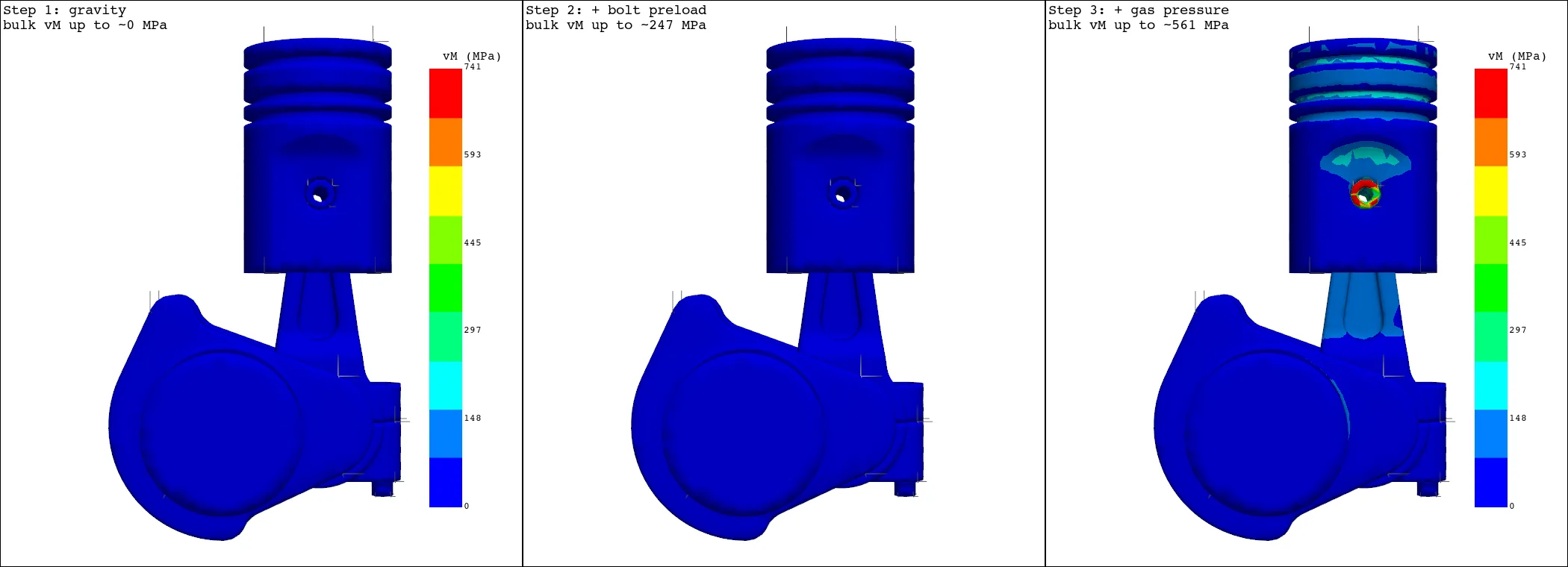
Von Mises at the end of each load step (shared 0–741 MPa scale). Step 1
(gravity) is essentially unstressed — the assembly just settles. Step 2 (+ bolt preload)
brings the bulk field up to a few hundred MPa as the cap bolts clamp the rod cap, but nothing is hot yet.
Step 3 (+ gas pressure) is where it happens: the firing load drives into the piston crown, down the
rod, and concentrates at the wrist-pin bore (red), with secondary lighting-up at the piston ring grooves and the rod
shank. The hot spot does not exist until the gas load arrives, and when it does it lands exactly on the contact
interface — not in the bulk of any single part.
Why the pin governs and the crank is comfortable
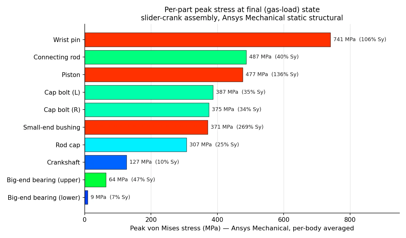
Ranking the per-part peaks makes the load path legible. The bar chart below is the von Mises maximum on each
body at the final (gas-load) state, as reported by Ansys Mechanical's per-body averaging — the same numbers
quoted in the result box, now visual and ranked.
Per-part peak von Mises at the firing state. The wrist pin tops the chart at
741 MPa, the connecting rod (487) and piston (477) follow, and the crankshaft sits
comfortably low at 127 MPa. Bars are tinted by fraction of each part's own yield strength, which is why
the pin and piston read hot even though the rod carries a higher absolute stress — the rod is high-strength
4340 steel with plenty of margin, while the pin and the aluminum piston are closer to their limits.
The reason the wrist pin governs is geometric: it carries essentially the entire gas load across the
smallest contact patch in the mechanism. The gas force on the piston crown funnels through the pin–bore interface,
a short cylinder loaded over a narrow bearing arc, so the contact pressure — and the von Mises just beneath it
— is the highest anywhere. The crankshaft is comfortable for the opposite reason: by the time the load
reaches it, it has spread across the big-end bearing and a much larger, stiffer section, so the same force produces a
fraction of the stress. That is the load path in one sentence — a concentrated point at the top, diffused into
bulk material by the bottom — and it is exactly the story a single-part model of the crankshaft (or the pin)
in isolation would get wrong.
How the whole thing moves
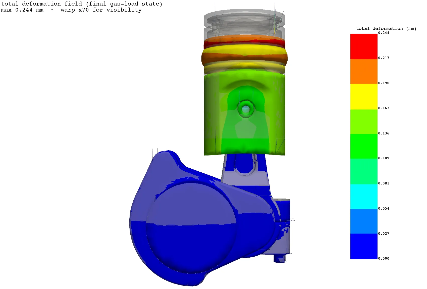
Total deformation field at the firing state (warped ×70 for visibility; undeformed shape ghosted).
Peak motion is about 0.24 mm at the piston crown, decaying down through the rod and into the near-rigid
crank throw. The picture captures the two kinematics the assembly couples that a part-model cannot: the piston
translating under gas load and the connecting rod swinging on the pin.
The modal and buckling pass, made visible
The companion analyses were named in passing before; here they are. Both ride on the same solved
assembly — the modal pass is pre-stressed by the static load, and the buckling pass reports how much more load
the structure could take before it goes unstable.
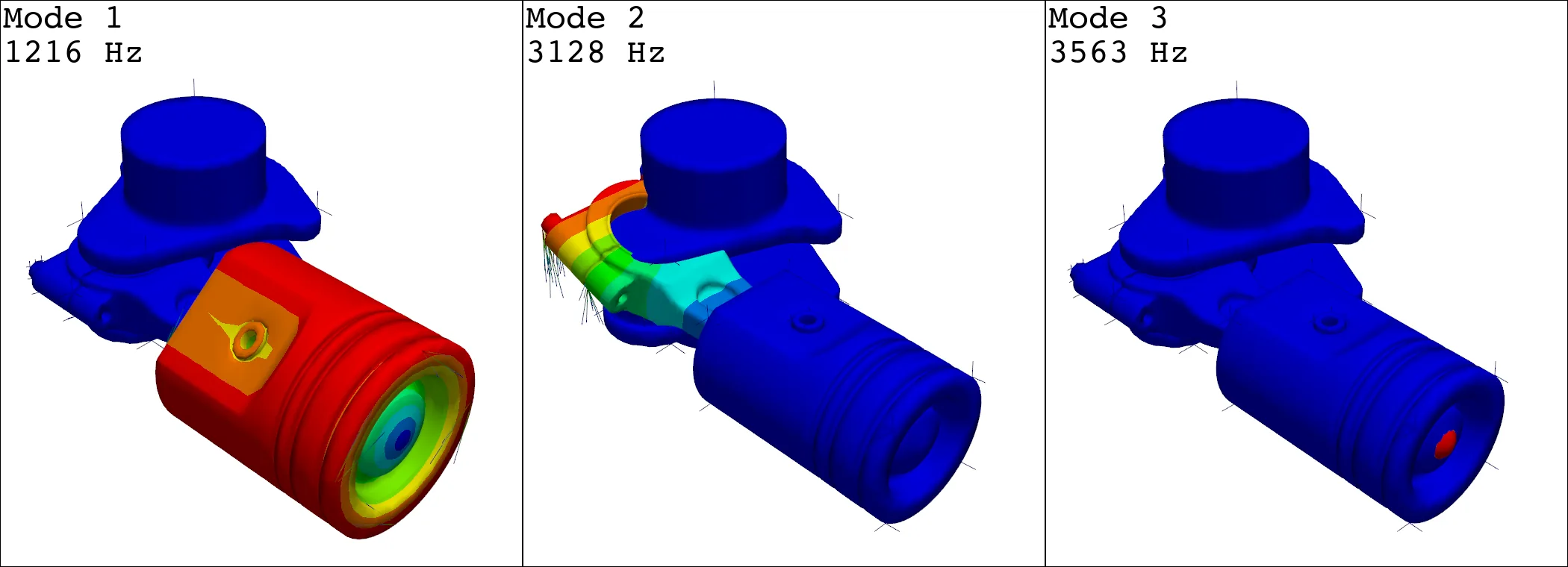
First three pre-stressed mode shapes of the assembly. Mode 1 at 1216 Hz is a local
pin/piston-pin-boss motion; Mode 2 at 3128 Hz is a connecting-rod bending shape; Mode 3 at
3563 Hz is higher-order. The lowest natural frequency sitting above 1 kHz says the mechanism is stiff
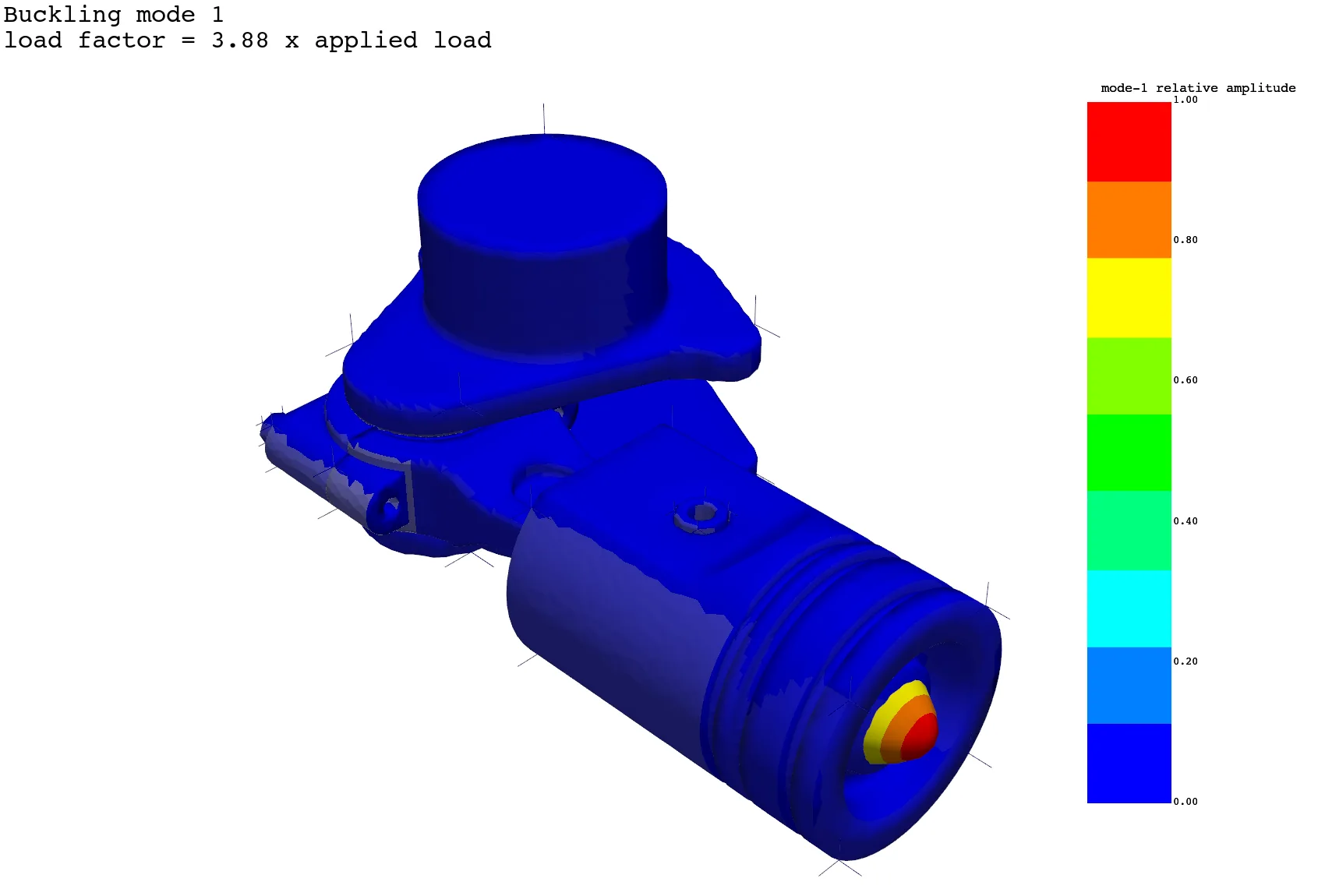
relative to typical firing-frequency content — useful context for whether any forcing could resonate.First linear-buckling eigenmode, with a load factor of 3.88 — the applied load would have to
grow roughly 3.9× before this mode becomes unstable. The mode localizes at the slender pin end, the same
region that carries the peak stress, which is consistent: the most heavily loaded, least supported feature is both the
stress hot-spot and the first thing to go unstable. A factor near 4 is a healthy margin against elastic instability
for this load case.
Why this one matters
Honest scope. Multi-step linear-elastic static structural with frictional contact on an
idealized nine-part assembly; the gas load is a representative firing pressure, not a measured cylinder trace. The
dirty-STEP bonding (corner node-welds, skirt bore-guidance) is a pragmatic recipe to make the imported geometry
solvable; two independent build routes agree, which is the cross-check. On the numbers: the per-part peaks
(741 / 487 / 477 / 127 MPa) are Ansys Mechanical's per-body averaged
von Mises maxima — local contact-region values that should be read as the assembly's stress distribution,
hot-spots and ranking, not certified allowables or a durability sign-off. The section, deformation, mode-shape and
buckling figures are rendered directly from the solved result file; the contour scales on the cut and load-path plots
are capped at the per-body assembly peak so a numerical contact singularity does not wash out the bands. We had
planned a contact-pressure section as well, but contact-stress output was not written to this result file (only contact
status was), so we show the solid von Mises through the cut instead rather than invent a field that is not there.
The whole reason to model an assembly instead of a part is that the dangerous stresses are at the interfaces —
the pin bore, the rod small-end, the bolted joint — and those simply don't exist in an isolated single-body run.
Getting there means solving the unglamorous problems first: making dirty CAD watertight enough to mesh, killing the
rigid-body modes that stall the solver, and applying the load in the order it really arrives. Do that, and the contour
plot tells you where the machine actually works hardest. Innovation through insight.
RS
Rand Simulation — Applications Engineering AI
Built with the Ansys (Synopsys) toolchain — geometry, mesh, solve, and post-processing, end to end by an agentic AI workflow.
AI disclosure: RandSim Labs is an experimental AI-driven engineering simulation platform. Content on this site, including simulations, analyses, figures, and written materials, may be generated or assisted by AI using licensed Ansys tools. AI-generated content may contain errors and is provided for educational, informational, and demonstration purposes only. Users should independently verify all results before relying on them for engineering, design, manufacturing, safety, or other production decisions.