
What Really Breaks a Carbon Drone Arm? We Crashed One in LS-DYNA, Then Judged the Layup in ACP
Sizing a composite part always comes down to one deceptively simple question: what load do you design against? For a carbon quadcopter arm, the honest answer is “whatever a crash does to it” — and a crash is a messy, millisecond-long impact, not a tidy number you can read off a napkin. So we did the two-step version of the problem the way an analyst actually would. First we built a rough quadcopter and crashed it in Ansys LS-DYNA — a real explicit-dynamics impact — to derive the load the arm root actually feels. Then we fed that load into an Ansys Composite PrepPost layup and asked DPF Composites which ply cracks first. The derived load did not match the desk estimate we started with. It wasn’t even close — and it changed the answer.
Why not just estimate the load?
You can, and people do. The back-of-envelope version goes like this: a 1.5 kg quad has four arms, so each arm carries about 0.375 kg of airframe; assume a hard landing arrests that mass at, say, 35 g; multiply out and you get a tidy 130 N at the motor mount. It is a reasonable first guess. It is also built on two assumptions you cannot check without simulating the crash: that 35 g is the right deceleration, and that the worst-loaded arm is the one carrying its own share of the mass straight down.
An explicit crash makes no such assumptions. It resolves the contact, the rotation, and the whip of every arm in time. The trade is that it hands you a time history, not a single number — so the analyst’s job becomes reading the real load out of it. That is exactly what the cross-section force at each arm root gives you.
What the arm root actually feels
We instrumented a cross-section at each of the four arm roots and recorded the bending they carry through the impact, then converted each to the equivalent static tip force — the steady tip load that would produce the same root bending, so it can be compared apples-to-apples against the layup’s strength. Two very different stories came out of the same crash.
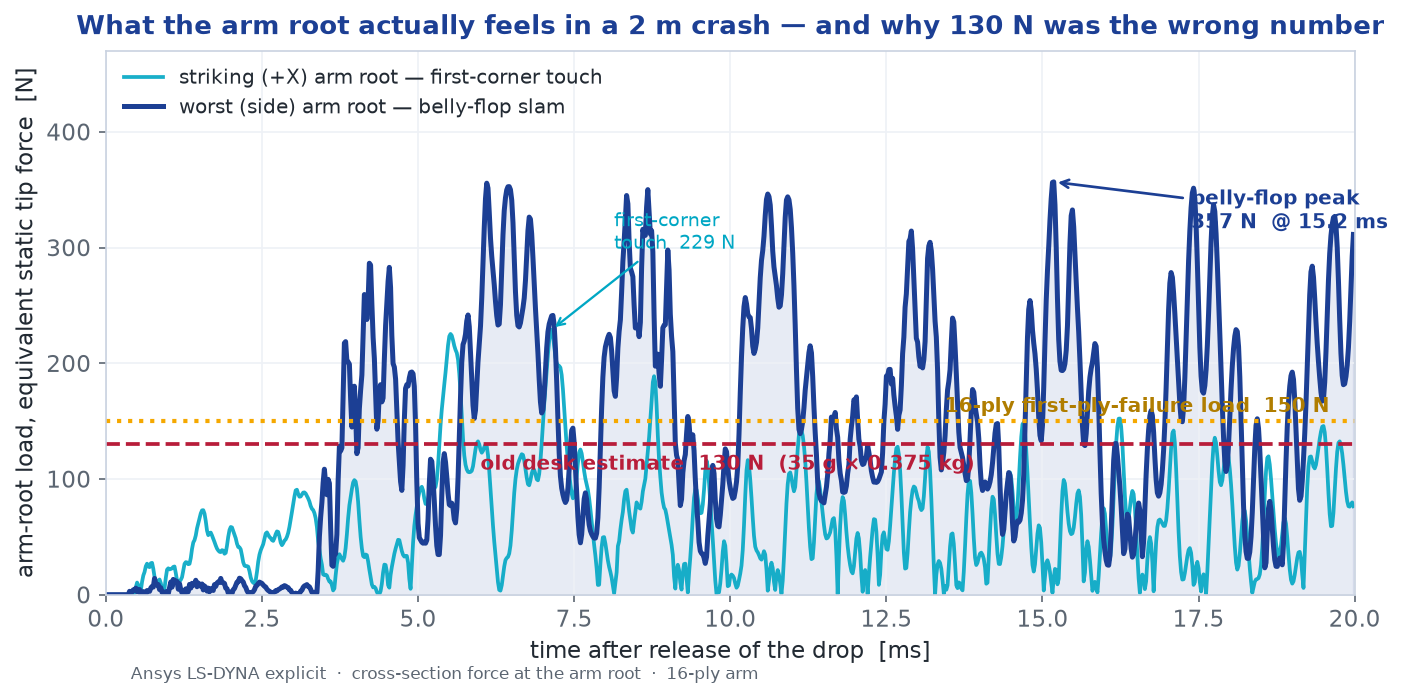
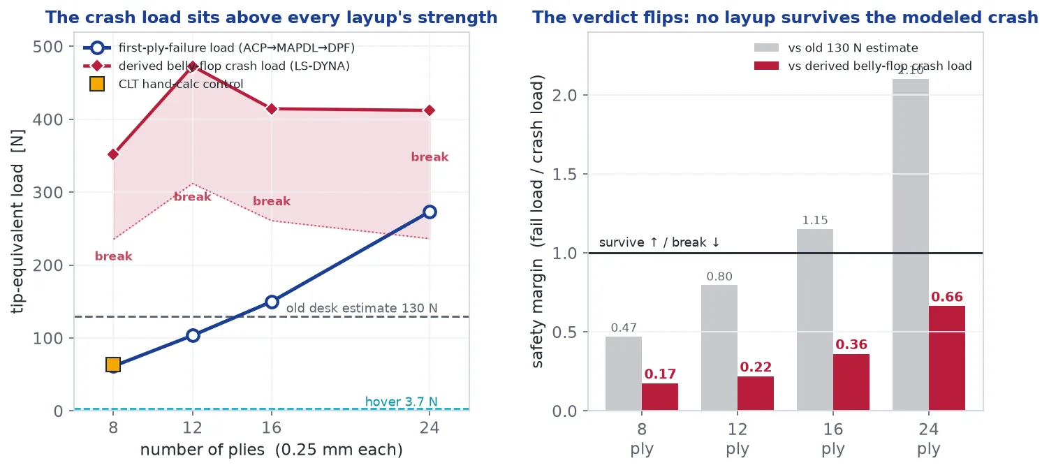
This is the payoff of doing the crash instead of guessing. The desk estimate wasn’t simply conservative or unconservative — it was aimed at the wrong event. The arm that hits the ground first is protected by the rotation it triggers; it sheds load as the frame pivots off it. The arms that pay for that rotation are the two along the tilt axis, which get slammed flat a few milliseconds later with the motor masses driving them. Even after filtering the trace to knock down the sharpest transients, that belly-flop load lands in the 219–357 N band (heaviest filtering to raw) — and the verdict below holds anywhere in it: even the most heavily filtered value sits half again above the 16-ply arm’s 150 N strength.
The layup, and what cracks first
Now the composite half. A single unidirectional carbon ply is a bundle of fierce, stiff fibers in soft epoxy: pull along the fibers and it carries 1500 MPa; pull across them and you are only loading the epoxy between them, which lets go at about 50 MPa — thirty times weaker. The whole art of a laminate is to stack plies at angles so some fibers always point at the load. A [0/45/−45/90]s stack — the classic quasi-isotropic layup — behaves roughly the same in every in-plane direction.
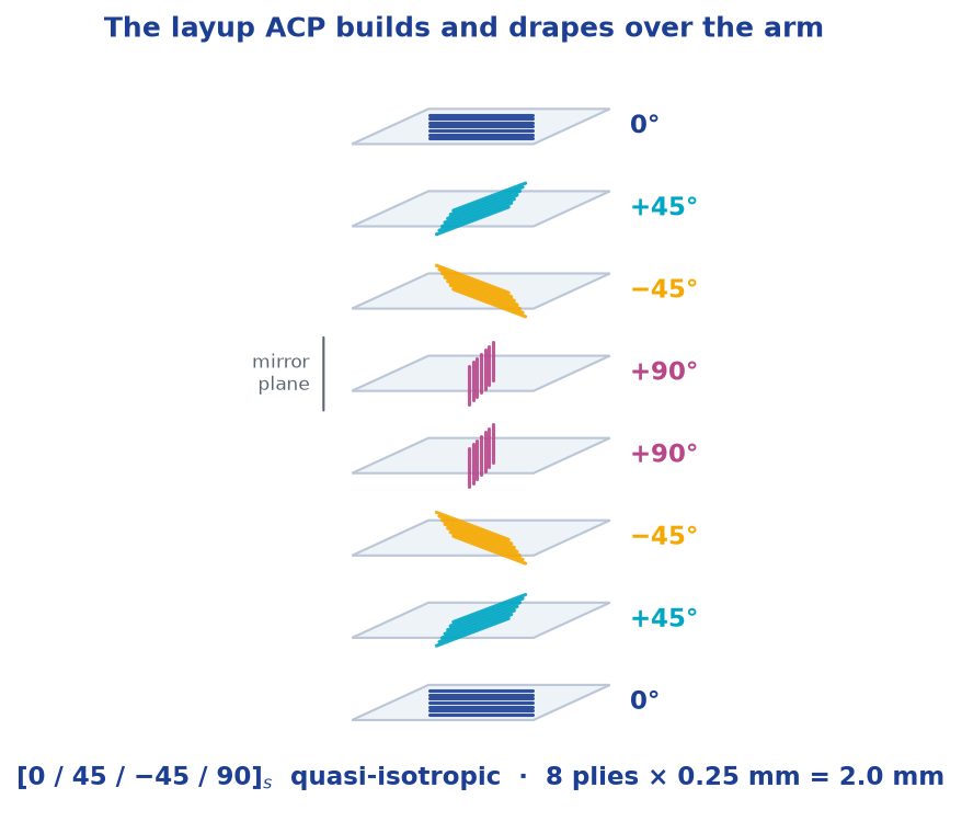
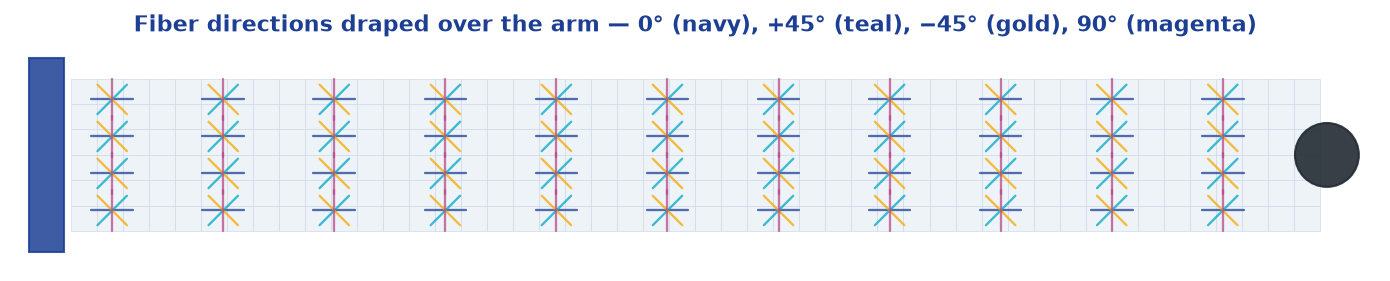
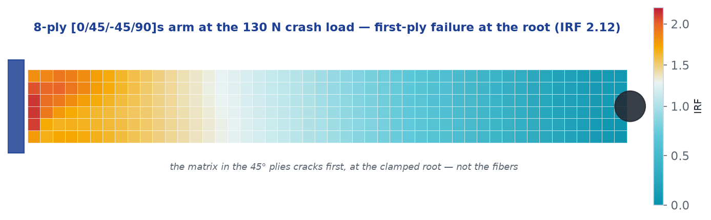
But there is a catch the slogan never mentions. When the arm bends, the plies whose fibers point across the bending still have to carry their share, and they can only do it through that weak matrix. So the first thing to fail in a well-designed laminate is usually not a fiber snapping — it is the matrix cracking in an off-axis ply. Engineers call it first-ply failure, and it is the number that sizes the part. We build the arm as a 288-element layered SHELL181 model in ACP, solve the bending in Ansys Mechanical with per-layer stress output, and let DPF Composites evaluate the combined Puck / Max-Stress failure index in every ply, at the load the crash derived.
The verdict: you cannot out-ply this crash
Here is the subtlety that makes this a genuine two-tool problem rather than two separate ones. A thicker arm is stiffer — and a stiffer arm, slammed against rigid ground, draws a higher slam load. The load and the strength both move when you add plies. So we crashed each layup on its own — 8, 12, 16 and 24 plies — and compared each arm’s derived crash load against its own first-ply-failure strength.
Is it right?
Two independent controls, one for each tool. On the composite side, we recomputed first-ply failure the old-fashioned way — Classical Laminate Theory, by hand, in a few lines of NumPy: assemble the laminate’s bending stiffness, apply the same root moment, walk each ply against its strength limits. The hand-calc puts first failure at 63.2 N for the 8-ply arm; the full ACP → MAPDL → DPF chain says 61.4 N — a 2.9% difference between a closed-form calculation and a layered-shell finite-element solve.
One scaling check does not close, and it belongs in the open. The 8-, 16- and 24-ply arms are scaled repeats of the same stack — [0/45/−45/90]s, [0/45/−45/90]2s, [0/45/−45/90]3s — so classical laminate theory says their first-ply-failure loads should grow with the square of thickness: 4× from 8 to 16 plies, 2.25× from 16 to 24. The solved chain grows slower: 2.4× (61.4 → 150 N) and 1.8× (150 → 273 N). The deviation grows with thickness — the solve sits at 97% of the classical strength at 8 plies, 59% at 16, 48% at 24 — and the likeliest seat is the clamped-root boundary, a stress riser the hand theory does not carry and the layered-shell solve resolves differently as the laminate thickens, though pinning the mechanism down would take a dedicated pass. The 2.9% CLT agreement above was demonstrated at 8 plies only. (The 12-ply arm is a different stacking family, [0/45/−45/90/0/90]s, so t² does not directly apply to it.) The direction of the gap is conservative — the solved strengths are lower than classical scaling would claim — and the verdict is insensitive to which curve you believe: even on the classical t² curve built from the CLT hand value (63.2 × 4 = 253 N at 16 plies, 63.2 × 9 = 569 N at 24) every layup in the sweep still breaks against its own crash load.
On the crash side, we halved the drop height and re-ran, and two clean bounds bracket what should happen. If the impact behaved as a single linear spring, the peak load would scale with the square root of drop height — impact energy grows with h, a linear spring stores it as F²/2k, so a doubled drop raises the load by √2 ≈ 1.41×. If instead the structure crushed at constant force over a fixed stroke, the load would scale with the height itself — 2.0×. The measured crash refuses to pick either, and not by a little: the belly-flop side-arm peak rose 1.46× (357 vs 244 N raw; 1.44–1.50× across filter widths), just above the linear-spring bound — while the striking arm’s first-corner load rose 2.31× (229 vs 99 N), past even the constant-stroke bound. No single scaling law maps the half-drop onto the full drop; the crash redistributes load among the arms as the event itself changes with severity, which is precisely why it earns an explicit simulation rather than a scaled hand estimate. By contrast the static bending in ACP is exactly linear: doubling the tip load doubled the failure index to four significant figures (ratio 2.000), confirming the composite solve sits squarely in the small-deflection regime where these numbers are valid. Each of the four full-drop crashes — the runs behind the published loads — closed its energy balance to under 2% with zero hourglass energy, the LS-DYNA signature of a clean solve (the half-drop control ran a touch looser at ~6% on its smaller energy budget).
The real-world connection
This is why quadcopter arms are almost always bolt-on and sold in packs. The crash load doesn’t reward carbon the way a static bending case does, so racers and cinematographers treat arms as consumables and design the airframe to sacrifice them gracefully. Where carbon still wins outright is weight in flight: an aluminum arm of the same bending stiffness as our 16-ply carbon one weighs 42.8 g against 24.9 g — carbon comes in 42% lighter, and every one of those grams sits at the far end of a spinning arm where it costs flight time and agility. The two answers live together: carbon for the everyday flight loads, a replaceable-arm strategy for the crash. And getting there took both tools — LS-DYNA to say what the load is, ACP and DPF Composites to say whether the laminate survives it. Change the layup, re-drape, re-evaluate; change the drop, re-derive the load. That loop is the workflow.
Sizing a composite part where the load itself has to be earned? The hard part is often not the layup — it’s pinning down the load the part actually sees, then judging the laminate against it. Chaining an explicit LS-DYNA event into an ACP → DPF Composites first-ply-failure check is exactly the kind of end-to-end workflow the Ansys toolchain is built for. If you’re weighing a design like it, we’d enjoy the conversation. Innovation through insight.