Why a Curveball Bends: The Magnus Effect in CFD
A curveball that drops off the table. A topspin forehand that dives into the corner. Roberto Carlos's 40-yard free-kick that started ten yards wide of the post and then, impossibly, boomeranged back inside it. Three sports, one piece of physics: a spinning ball in moving air feels a sideways force. It's called the Magnus effect, and we put a spinning cylinder into Ansys Fluent, dialed the spin up and down, and measured exactly how hard that invisible hand pushes.
The physics: spin steals symmetry
Drop a non-spinning ball into a steady airflow and the picture is symmetric — equal flow over the top and bottom, no net sideways force. Now spin it. The surface drags a thin layer of air around with it. On the side where the surface moves with the oncoming stream, the flow speeds up and the pressure drops; on the opposite side it slows down and the pressure climbs. That pressure imbalance is a force pointed straight across the flow direction — the Magnus force. Spin faster and the imbalance grows, so the force grows with it.
That's the whole trick behind a pitcher's curveball, a tennis player's topspin dip, and a bending free-kick. The ball doesn't curve because it's clever; it curves because spin breaks the flow's symmetry and the pressure field does the rest.
No spin, no curve. Add spin and a sideways force appears out of nowhere — except it isn't nowhere, it's a measurable pressure difference, and CFD can read it straight off the cylinder wall.
Inside the model
Geometry and mesh
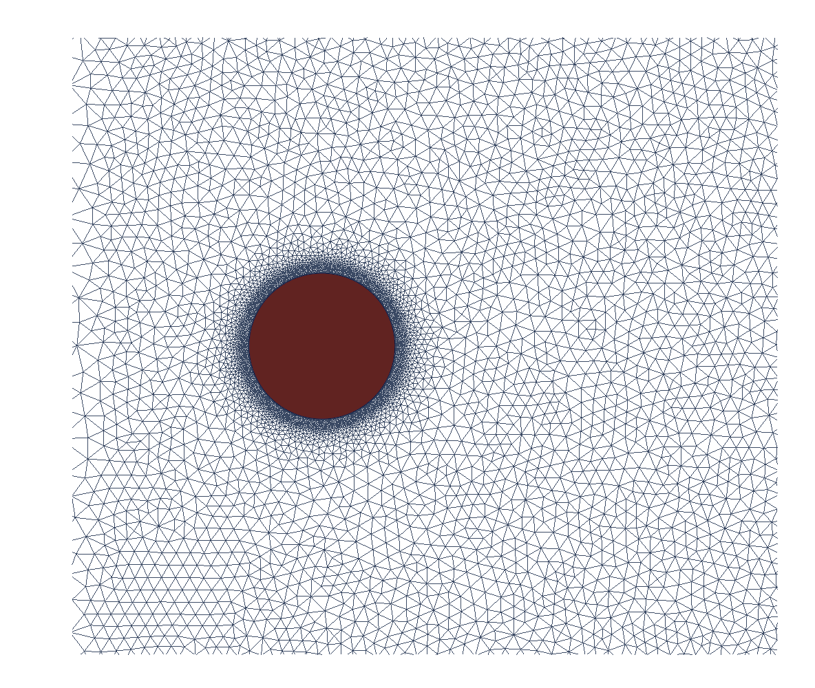
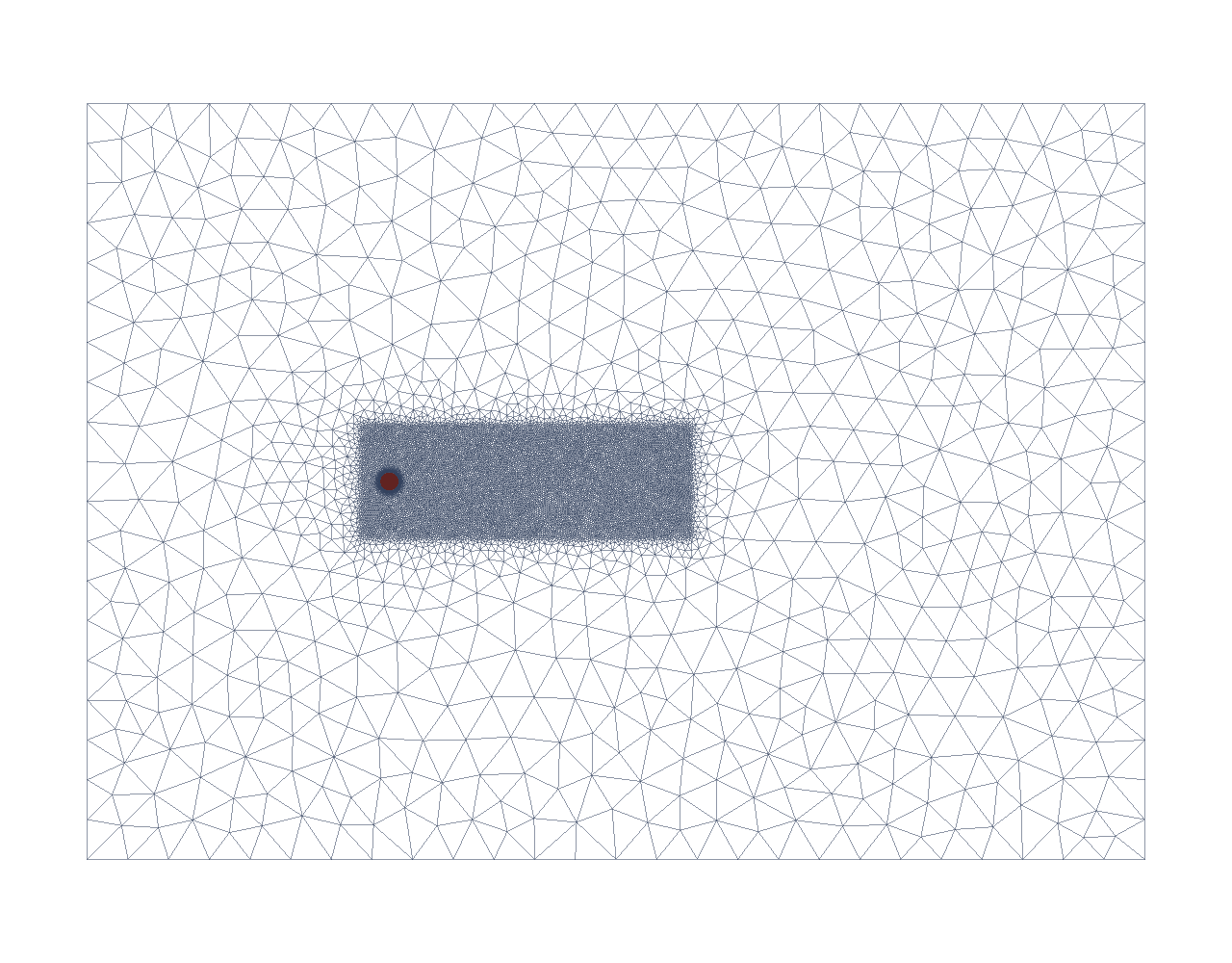
We used the classic 2D analog of a spinning ball: an infinite spinning cylinder, diameter d = 1, in a uniform freestream U = 1. The domain is a generous box — about 16 diameters across and 40 long — so the walls and outlet never crowd the wake. The mesh was built in gmsh using its OpenCASCADE kernel, with a fine boundary-layer ring hugging the cylinder wall (where the pressure gradients live) and a refined wake box trailing downstream. Total: 36,816 triangular cells.
Setup, BCs, and solver
The case is a 2D laminar transient simulation at Re = 200 — deliberately matching the published benchmark's regime rather than a real ball's Reynolds number (more on that in the honest-scope box). The spin enters through the cylinder boundary condition: a rotating moving wall in Fluent, with the rotation speed set to ω = α·U/R for each target spin ratio α. We verified the wall-motion setup — a moving wall, rotating about the cylinder axis at ω — before trusting any numbers.
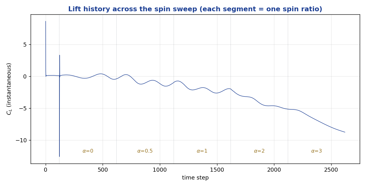
Numerics: SIMPLEC pressure-velocity coupling, second-order in both space and time, time step dt = 0.05. A key efficiency decision: rather than cold-start five separate cases, we ran one warm-started sweep in Fluent — α = 0, 0.5, 1, 2, 3 — letting each spin ratio inherit the converged field from the one below it, 500 steps per setting. That's why the lift-history plot reads as one continuous story rather than five disconnected runs.
The result
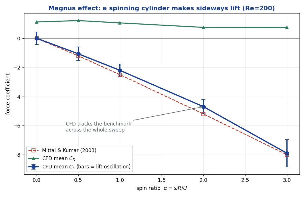
Spinning the cylinder produced exactly the sideways lift the Magnus effect predicts, and it grew with spin in a near-linear march. At zero spin, the mean lift is essentially zero — symmetric flow, no Magnus force — and by α = 3 it has climbed to a mean CL of nearly −8. Drag, meanwhile, falls as spin rises: the spinning wall re-streamlines the wake.
Is it right?
The gold-standard reference for this exact problem is Mittal & Kumar (2003), "Flow past a rotating cylinder" (J. Fluid Mech. 476:303–334) at Re = 200. Our model lands right on it: the low-to-moderate-α lift slope of 2.36 sits just under the benchmark's ~2.5–2.6, the magnitude at α = 2 (−4.70 vs. ~−5.2) and α = 3 (−7.90 vs. ~−8.0) are within the ~5–15% spread typical of CFD benchmarks across mesh and scheme, and the no-spin case is symmetric to within 1% of zero as it must be. The sign just follows the spin direction — we report magnitudes. Slope, magnitude, and the α=0 sanity check all agree.
The real-world connection
This is the physics that humbled a defending world champion. On June 3, 1997, in the opening match of Le Tournoi at Lyon, Brazil's Roberto Carlos lined up a free-kick 40 yards from the French goal. He struck it with the outside of his left boot at around 137 km/h, loaded with sidespin. It set off heading ten yards wide of the post — French keeper Fabien Barthez reportedly didn't even move — and then the Magnus force took over, bending the ball back through the air and inside the post. (Carlos has cheerfully admitted the wind helped; four French physicists were inspired enough to publish a new free-kick equation in the New Journal of Physics over it.) It's the same CL we just measured — only on a leather sphere instead of a cylinder.
The same force shows up wherever spin meets a flow. A baseball curveball carrying roughly 1,800 rpm bends a couple of feet over its 60-foot flight — enough to slide past a bat swung at where the ball "should" be. A tennis or table-tennis topspin shot points the Magnus force downward, letting a player swing harder while the ball still dips into the court. Different sports, different equipment, one identical mechanism — and a compact CFD model reproduces the heart of all of it.
When the force that makes or breaks your design is one you can’t see, how do you know your CFD number is right? Ansys Fluent sweeping a rotating-wall cylinder through five spin ratios on a 36,816-cell gmsh mesh, warm-started and second-order, then held against Mittal & Kumar’s published Re = 200 benchmark — lift slope 2.36 vs. ~2.5–2.6, mean CL −7.90 at α = 3 vs. ~−8.0, and zero lift at zero spin to within 1% — is how simulation puts a validated number on an invisible force before a prototype has to find it the hard way. That's innovation through insight.