Why a Strong Magnet Pushes Against Its Own Coil
Ask most people what limits how strong a magnet can be and they will say power, or heat. Those matter. But there is a more fundamental wall, and it is structural: a magnetic field stores energy, and that stored energy presses on whatever confines it. Inside a solenoid the field is axial; the current in the windings is azimuthal; and the cross product of the two is a force that points radially outward, everywhere in the coil. A strong magnet is, quite literally, always trying to blow itself open.
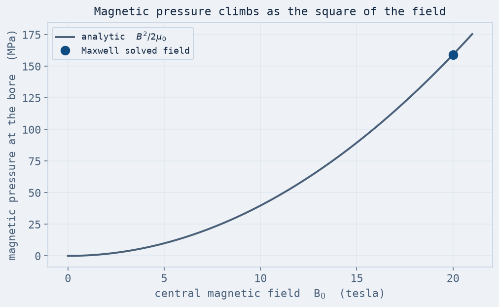
The size of that push is the magnetic pressure, and it has a clean form: the energy density of the field, B²/2μ₀. It is quadratic in the field, so it bites hard. At 10 tesla it is about 40 MPa — a few hundred atmospheres. At 20 tesla it is roughly 159 MPa, comparable to the yield strength of the copper the coil is wound from. The field a magnet makes and the stress it must survive are the same physics, seen twice.
Solving it, not just estimating it
The pressure formula is the back-of-envelope. To get the real stress you need the real field and the real geometry, because a thick winding is not a thin shell — the force is spread through its volume, and the hoop stress that resists it varies from the bore to the outer layer. So the study runs in two Ansys solves that hand off to each other.
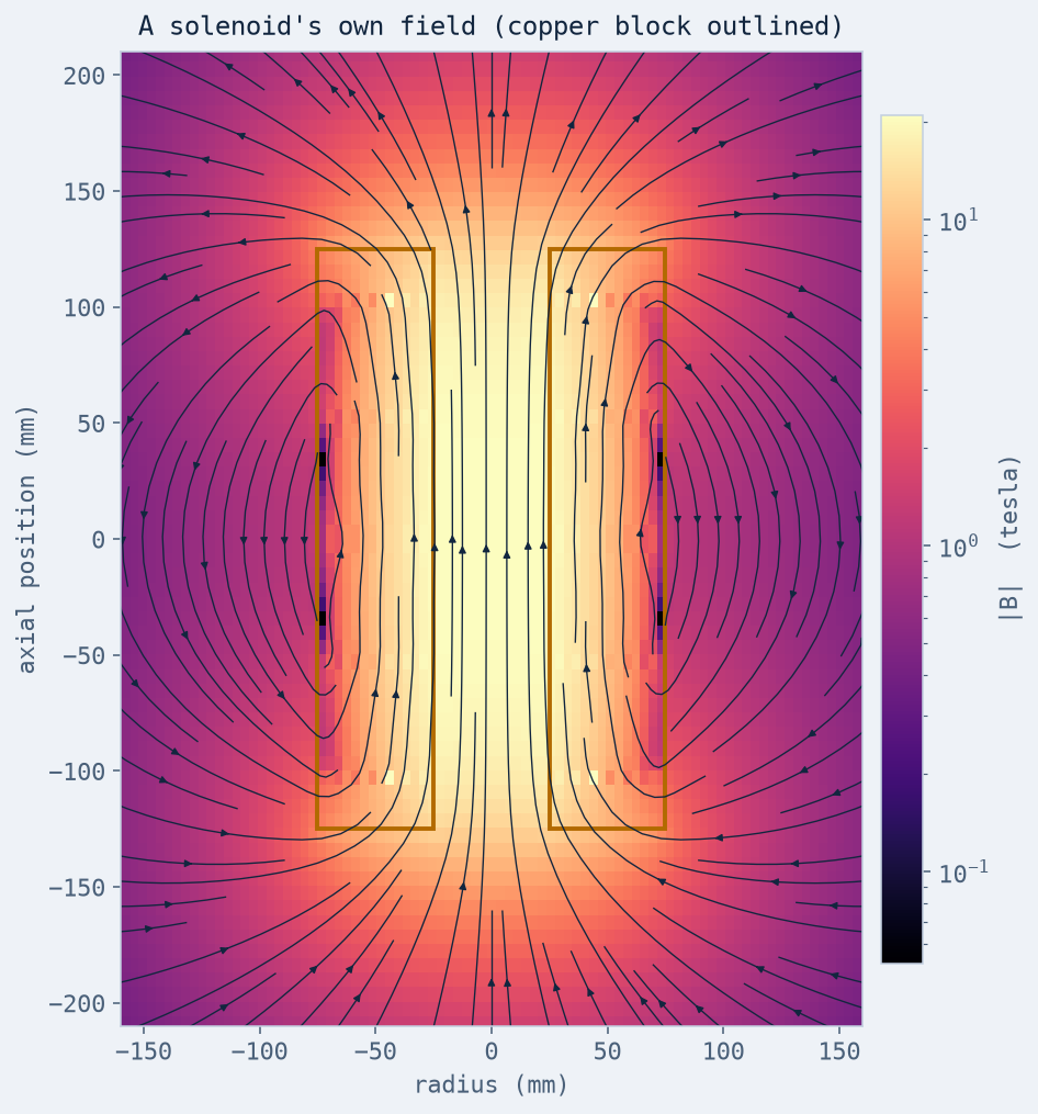
First, Ansys Maxwell converges the magnetostatic field of the energized coil. Because an air-core magnet is electromagnetically linear, that field is captured exactly by the closed-form loop-superposition law — a central field of about 20.5 tesla at the design current, scaling linearly with it — and the two agree, which is the check that the field is right before it drives anything. One bookkeeping point, so the numbers reconcile rather than merely coexist: the structural sweep is parameterized by central field and run at exact levels, so every “20 T” stress in this article is at 20.0 T. The nominal design current — sized from the simple finite-solenoid formula — actually produces about 20.5 T once the winding's full geometry is summed, roughly 2.4% more field and therefore (stress scaling as B²) about 5% more stress than the 20 T figures quoted here. It is this validated field whose axial component, times the winding current density, gives the radial body force point by point.
Second, Ansys Mechanical APDL takes that body force onto an axisymmetric model of the winding cross-section and solves for the stress and the deflection. Modeling the field-coupled body force directly (rather than a single smeared pressure) is why this half runs in MAPDL: the load is a field, applied element by element, and the solver returns the stress the copper actually feels — hoop-dominated through the pack — and the radial growth, the “bloom,” that goes with it.
Where the coil gives up
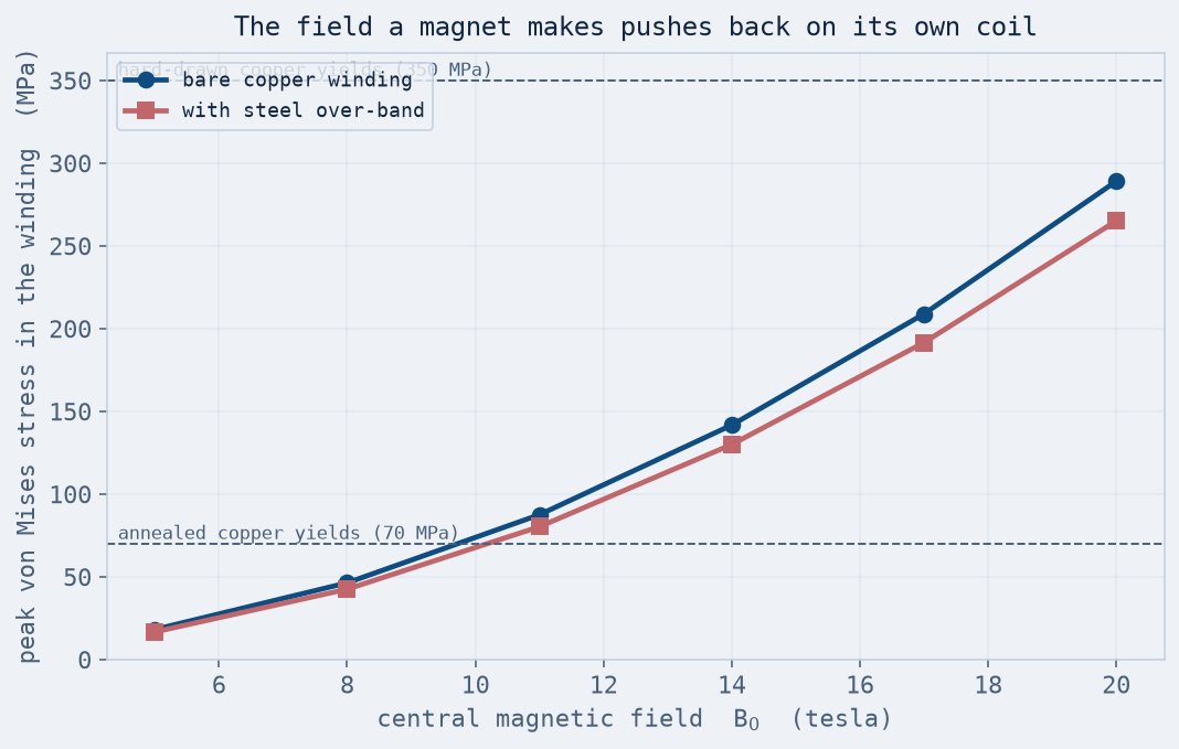
The stress curve is the payoff, and the crossings on it come straight from the solved curve — peak stress grows as B², so each yield strength maps to a field. For a bare copper winding the peak stress reaches annealed copper's yield (70 MPa) at only about 9.7 tesla — well short of the fields modern magnets reach. Cold-worked (hard-drawn) copper at a 350 MPa yield buys headroom to about 22 T on the same curve. The steel over-band is the humbling one: the banded solves show a 10 mm steel band trims the copper's peak stress by only about 8% (289 → 265 MPa at 20 T), because the stress peaks at the bore and a band on the outside of a 50 mm-thick winding barely reaches it. That moves the hard-drawn copper's ceiling from about 22 to about 23 T — one extra tesla, not twenty. (An earlier version of this article quoted 29.66 T and 41.94 T for these two upgrades; both were crossings of the smooth B²/2μ₀ pressure line against the 350 and 700 MPa yields — a curve that drops the very ~1.8× concentration factor this article exists to demonstrate. On the solved curve, the copper would be near 1.3 GPa at 42 T — failed several times over.)
At 20 tesla the modeled bare coil shows a peak stress near 289 MPa and a radial bloom of about 0.06 mm — small in absolute terms, but past yield, which for a magnet means turns that shift, insulation that works, and a coil that does not come back to the same shape it started in.
It is worth noting how far the solved stress sits above the tidy magnetic-pressure number. At 20 tesla the bore pressure B²/2μ₀ is about 159 MPa, but the peak equivalent (von Mises) stress the winding actually carries is roughly 289 MPa — about 1.8× as much (the hoop component itself peaks near 317 MPa, right at 2×). The reason is exactly why the thin-shell shortcut is dangerous: the outward force is not a pressure on a skin, it is a body force spread through the whole thickness of the pack, and a thick ring under a distributed radial load builds its highest hoop stress at the bore, well above the surface pressure. Size a coil on the pressure formula alone and you would think it had roughly double the margin it really has. That factor is the difference between a hand-calc and a solve.
The picture matches how real high-field magnets are actually built — including the gap. The strongest steady-state resistive magnets in the world — the water-cooled Bitter and poly-helix magnets at the national field labs — top out around the high-30s of tesla, well above this coil's ~23 T banded ceiling, and the difference is the lesson: they do not get there by wrapping a band around the outside. The reinforcement runs through the winding — plate-by-plate support in Bitter stacks, graded conductors, pre-stress applied before the field ever loads the bore — plus megawatts of cooling, precisely because the hoop-driven stress, not the current or the heat, is the ceiling. To go higher still you stop trying to hold the field steady: pulsed magnets reach a hundred tesla for a few milliseconds by letting the coil survive a stress it could never withstand continuously. Either way the design is a negotiation with the same B² force this study puts a number on.
Automation is the point
The value here is not one magnet — it is the map. One coil was built parametrically, the field was solved once in Maxwell, and the structural response was swept across 12 field-and-reinforcement cases in Mechanical, unattended, each one validated against the magnetic-pressure law before it was trusted. Turning “magnets have stress” into a stress-versus-field chart with a yield crossing on it is the everyday value of scripting two solvers to talk to each other.
Designing a magnet, an actuator, or a bus that carries serious field or current? The force the field puts on the structure is a solve, not a guess, and it is where a lot of high-field designs actually fail. We do coupled electromagnetic-structural work in Ansys Maxwell and Mechanical. Rand Simulation — innovation through insight.