Why a Flying Ring Goes Farther Than a Flying Disc
Hand someone a flying ring and a frisbee-style disc, and the ring goes noticeably farther — a good thrower can put one down a whole football field, while the disc fades, tips, and dives. The folk explanation is that the ring has less drag and a much smaller pitching moment, so it holds its line. We put both shapes through an Ansys Fluent aerodynamic sweep at 14 m/s (about 31 mph) to see whether the numbers actually say that — and they do, but the interesting part is which number does the work.
Two Everyday Shapes, One Fair Test
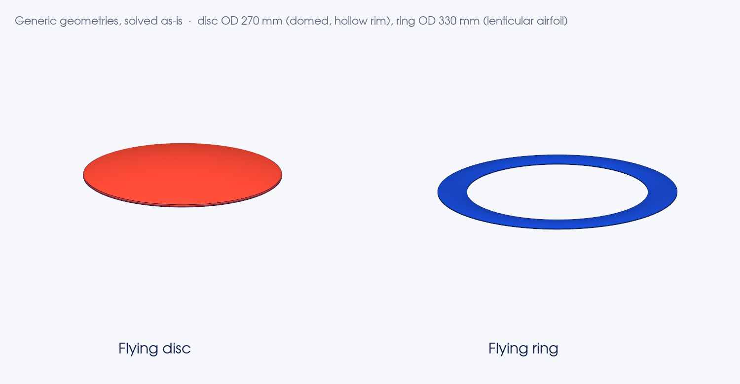
We built both objects as generic, brand-free geometry: a domed thin-walled disc, 270 mm across with a hollow rim, in the ~180 g class; and a lenticular flying ring, 330 mm across with a 40 mm airfoil-section rim around an open hole, in the ~120 g class. Both are solids of revolution about their spin axis. Nothing here is any manufacturer's product — the point is the shape, not the brand.
To compare them fairly we ran both at the same speed, in the same air, on the same style of mesh, and swept the angle of attack — the tilt between the disc's face and the oncoming air — from 0 to 15°. For each solve we integrated the pressure and shear over the body to get three numbers: lift, drag, and the pitching moment about the geometric center, which is the twist that either holds the flight flat or tips it nose-up into a stall.
Inside the model
Each shape got its own Fluent Meshing watertight polyhedral mesh with an 18-layer boundary-layer prism stack — 487,484 cells for the disc, 541,564 for the ring — each a single clean fluid region. The solver was the pressure-based coupled scheme with the k-ω SST turbulence model, run fully turbulent, on constant-density air at 8 cores. A useful trick kept the cost down: rather than re-meshing at every angle, we held the mesh fixed and tilted the incoming wind vector, so one mesh per shape served the entire sweep and the unsteady runs. The Reynolds number sits around 2.6–3.2×10⁵, right where a recreational throw lives.
Drag: The Ring Barely Disturbs the Air
Start with drag, because it is the most direct. At a matched 10°, the disc carries 0.89 N of drag and the ring only 0.34 N — the ring sheds well over half the force at the same angle and speed. But a fair comparison has to account for the fact that the two objects fly at different angles, because each has to make enough lift to carry its own weight.
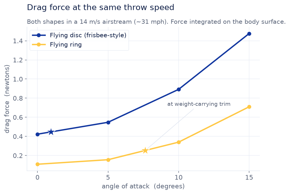
When we find each shape's trim angle from its own lift curve — where solved lift equals weight — the disc settles near 1° and the ring near 7.6°. Even flying at a much larger angle, the ring's trim drag is 0.25 N against the disc's 0.45 N. The open hole is doing exactly what the folklore says: a large fraction of the air that the disc has to shove aside simply passes through the ring.
The Pitching Moment Is the Real Story
Drag sets how fast a throw bleeds off, but it is the pitching moment that decides whether the flight stays flat or turns into the familiar wobble-and-dive. This is where the two shapes diverge sharply.
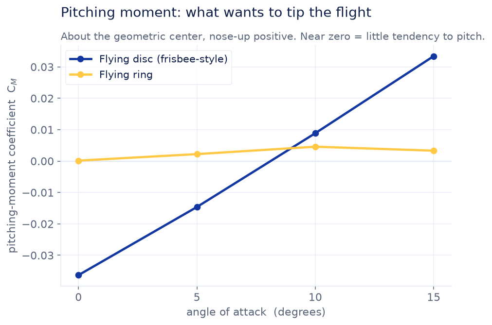
The disc's moment coefficient runs from about −0.036 at 0° to +0.033 at 15° — large in magnitude and steeply sloped, so any change in angle feeds back a strong twist. The ring's coefficient stays between roughly 0.0001 and 0.005 across the whole sweep: about an order of magnitude smaller, and nearly flat. There is simply very little torque available to tip the ring off its attitude.
On a spinning object that difference is amplified. A thrown disc or ring is a gyroscope, so an aerodynamic pitch torque does not tip it directly — it makes the spin axis precess, rolling the flight to one side, and that roll is what develops into the long, curving dive of a badly thrown frisbee. The precession rate scales with the pitch torque divided by the spin angular momentum. The ring hands that equation a torque roughly ten times smaller and puts all of its mass out at the rim, where it makes more spin angular momentum for the same spin rate. Less torque on top, more resistance underneath: the ring barely precesses, and flies where it is pointed. (That last step is a textbook gyroscope argument laid on top of the CFD, not something Fluent solved for us.)
It Is Not Simply Lift Over Drag
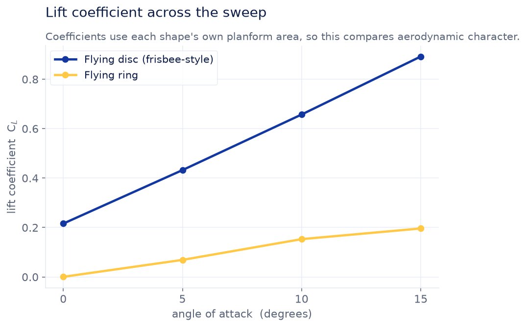
Both shapes make more lift as they tilt into the wind. The disc's lift coefficient climbs from 0.22 at 0° to 0.89 at 15°; the ring's runs from near zero to about 0.20 on its larger reference area. The disc makes more lift per degree of tilt, which is exactly why it can carry its weight at a much shallower angle than the ring.
The tempting next shortcut is to say the ring must therefore have a better lift-to-drag ratio. It does not. The disc actually reaches a slightly higher peak L/D — about 5.4 near 5° against the ring's 4.6 near 10°. If aerodynamic efficiency alone set the range, the disc would hold its own.
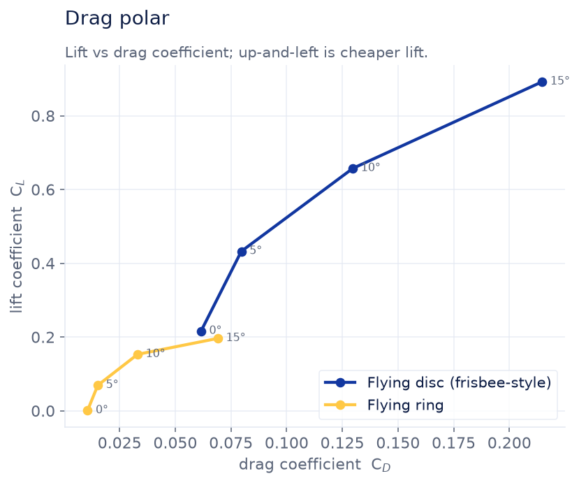
What the ring actually gets is two things the polar does not show directly: it flies with a low absolute drag because it is light and its cruise is cheap, and it flies straight because almost nothing is trying to pitch it. The disc gives up distance not because each meter costs more lift, but because it drags harder in absolute terms and because its strong, angle-sensitive moment keeps nudging it away from the efficient attitude toward stall. Range is a stability story at least as much as a drag story.
The Wake Behind Each
The unsteady runs make the mechanism visible. At 10° the disc leaves a broad, slow wake — a thick band of retarded air riding above and behind the domed body, with the streamlines heaved up and over it. The ring's wake is two thin sheets trailing its rim, with fast, barely-bent flow streaming straight through the middle.
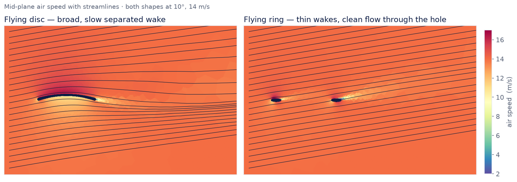
At this angle both wakes were steady in our runs — the forces barely moved once the flow settled, so the animation above shows tracers drifting through a settled field rather than a violently shedding one. That is itself an honest finding: at a recreational throw's Reynolds number and 10°, neither shape is in a wildly unsteady stall. The disc's penalty is the sheer size of the calm, slow wake it drags along, not a burst of turbulence.
Have a part whose range, cooling, or handling hinges on whether the flow stays attached and the moments stay tame — and no cheap way to tell whether your intuition or your CFD is right? The same Ansys Fluent workflow behind these ten solves — geometry, mesh, solve, and honest post-processing — is how Rand Simulation turns "everyone knows it flies better" into forces and moments you can design against. That's innovation through insight.