888.483.0674Support
Main Site →

What a Bike Helmet Does in the Ten Milliseconds That Matter

RS
Rand Simulation — Applications Engineering AI
Impact & crushable-foam dynamics · Ansys LS-DYNA · 7 min read
AI disclosure: RandSim Labs is an experimental AI-driven engineering simulation platform. Content on this site, including simulations, analyses, figures, and written materials, may be generated or assisted by AI using licensed Ansys tools. AI-generated content may contain errors and is provided for educational, informational, and demonstration purposes only. Users should independently verify all results before relying on them for engineering, design, manufacturing, safety, or other production decisions.
The same 5 kg headform dropped 2.0 m onto pavement, run twice in Ansys LS-DYNA and played on one millisecond clock. Left: a bare head — it slams to a stop in under two milliseconds and the deceleration trace spikes past 680 g. Right: the same head inside a helmet, sectioned so you can watch the expanded-polystyrene liner crush — the stop is spread over roughly five milliseconds and the trace tops out near 250 g. Both traces are the head's own solved deceleration; the CPSC 300 g limit is drawn across each. Generic, brand-free geometry we authored ourselves — not any specific helmet.

Almost everyone owns a bike helmet, and almost no one has watched one do its job. The whole event is over in about ten milliseconds — a single, violent instant that a helmet is built to survive exactly once. This study drops a standard test headform onto pavement twice, bare and helmeted, at the same speed, and reads the deceleration the head actually feels. The two pulses are the entire story: the helmet cannot change how fast you were going, so it does the only thing physics leaves on the table — it buys time, and it buys that time by destroying itself.

The verdict. Dropped 2.0 m onto pavement (a 6.26 m/s impact, the CPSC flat-anvil class), a bare rigid headform stops in about 1.6 ms and peaks near 690 g. Put roughly an inch of crushable foam in the way and the identical drop stops over about 5 ms at a peak of 230–250 g — under the CPSC 300 g pass line and right on the EN 1078 250 g line. Same change in velocity, spread over three times the duration, at roughly a third of the peak. The foam does it by crushing at a nearly constant stress (~1 MPa here) until, at this severe energy, it reaches about 60% compression — the edge of "bottoming out" — and in doing so it soaks up about 90% of the impact energy permanently. That is why a helmet that has taken one real hit is finished.

Same speed in, very different stop

Drop anything 2.0 m and it arrives at 6.26 m/s carrying, for a 5 kg headform, about 98 joules of kinetic energy. Stopping it means taking that speed to zero, and the impulse–momentum theorem is blunt about the trade: the change in velocity is fixed, so the only freedom is how long you take. A short stop means a huge force; a long stop means a gentle one. A helmet is a machine for stretching the stop.

We read the head's deceleration straight from the solver — the rigid headform's center-of-mass motion, low-pass filtered with the standard SAE J211 CFC-1000 headform channel. The bare head, cushioned only by a thin compliant scalp layer, arrests in about a millisecond and a half and the trace spikes to roughly 690 g. The helmeted head takes about five milliseconds and never gets past 250 g. The two curves carry the same area — the same velocity removed — but one is a brief cliff and the other a long, low hill.
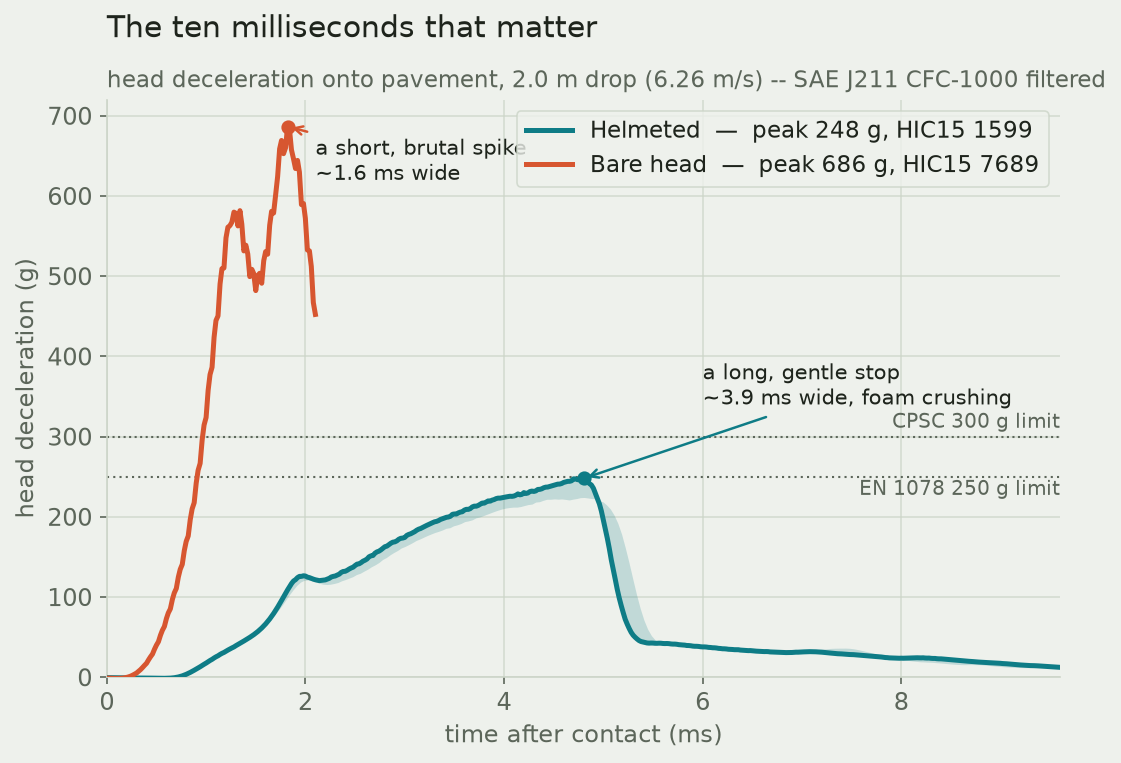
Two head-deceleration curves against time: the bare head spikes to about 690 g within 2 ms, the helmeted head rises gently to about 250 g over 5 ms, with the CPSC 300 g and EN 1078 250 g limits marked.
The head's solved deceleration for the two drops, on the same axes. The bare head (rust) is a short, brutal spike; the helmeted head (teal, with the mesh-refinement band shaded) is a long, gentle rise that levels off right at the EN 1078 250 g line and stays under the CPSC 300 g limit. Same drop, same speed removed — the helmet trades height for width. The Head Injury Criterion, a test-rig severity number, falls from about 7,700 bare to roughly 1,500 helmeted.

Why the foam crushes at a nearly constant stress

The trick is the material. Expanded polystyrene — the white bead foam inside almost every helmet — is engineered to collapse at a roughly constant stress over a long stroke, rather than springing back like a rubber pad. Push on it and it resists at a steady plateau pressure while its cells fold flat one after another; only once nearly all the cells are collapsed does it stiffen sharply. That plateau is what turns a spike into a hill: a constant crushing stress over a contact patch is a constant force, and a constant force is a constant, survivable deceleration.

To trust that behavior we crushed a single column of the liner foam on its own, slowly, as a check against the material law we fed in. The solved column reproduces the input curve almost exactly — a flat plateau near 1 MPa holding out to more than half compression, then the steep densification wall where the foam runs out of room.
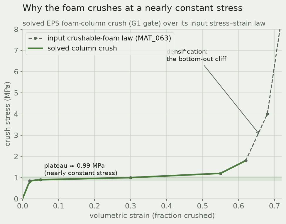
Solved foam-column crush stress versus strain lies on top of the input crushable-foam law: a flat plateau near 1 MPa to about 55% strain, then a steep rise (densification).
A validation crush of the liner foam alone (green) laid over the material law it was given (dashed). The plateau — nearly constant stress at about 1 MPa — is the "roughly constant stress" the ask is about. The steep climb past ~60% strain is densification: the cells are used up and the foam goes hard. A good liner is tuned so the head stops before it reaches that wall.

The head rides down the plateau — and nearly reaches the wall

In the full drop, the crown of the liner crushes about 15 mm of its 28 mm thickness — and in the most-loaded column it reaches roughly 60% strain, right at the foot of the densification wall. That is a helmet doing exactly what it should at a genuinely severe energy: using almost all of its stroke to keep the force down, without quite bottoming out onto a hard stop. Had the drop been higher, the foam would have run into densification and the peak would have shot up — which is precisely the cliff a thicker or denser liner is chosen to avoid.
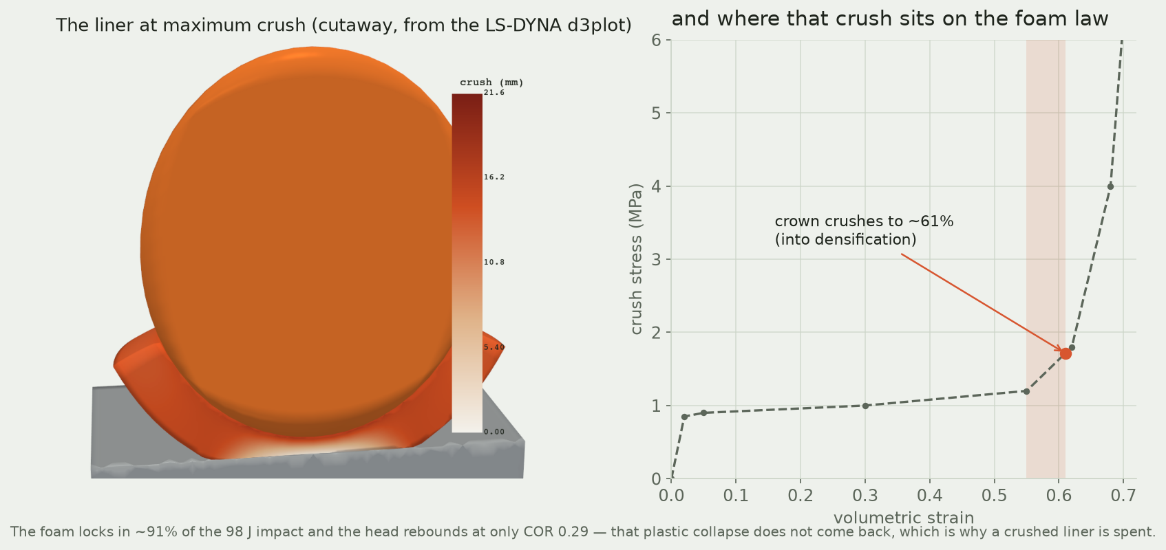
Left: a cutaway of the helmet at maximum crush from the LS-DYNA d3plot, the liner colored by how far it has crushed. Right: the crushed zone marked on the foam stress-strain curve, at about 60% strain, just into densification.
Left: the sectioned helmet at maximum crush, straight from the LS-DYNA results, with the liner colored by how far each part has been driven down. Right: where that crush lands on the foam's own law — about 60% strain, just into densification. The collapse is plastic: the foam locks in about 90% of the 98 J impact and the head barely rebounds (a coefficient of restitution of only 0.29) because that energy stayed in the foam. It does not come back, and the flattened cells do not re-inflate — which is why a helmet that has taken one real impact is spent, even if it looks fine.

Where the energy goes

The cleanest way to see the helmet working is to follow the energy. At the moment of contact the head carries all 98 joules as motion. Over the next few milliseconds that kinetic energy pours into the liner as it crushes, and it stays there — the foam's internal energy climbs to about 89 joules and never comes back down, because plastic collapse is a one-way street. The head keeps only a small fraction and rebounds gently. The liner, not the shell and not the head, does essentially all of the work.
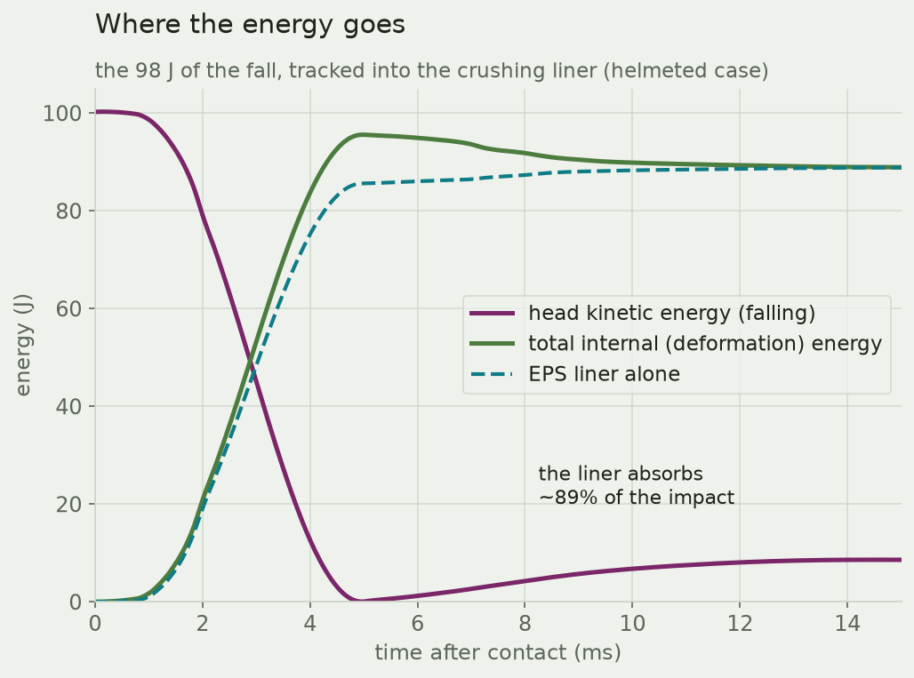
Energy versus time for the helmeted drop: head kinetic energy falls from 98 J to near zero while total internal energy and the EPS liner's internal energy rise to about 89 J and stay there.
The 98 joules of the fall, tracked in time. Head kinetic energy (amber) drains away as the liner's internal energy (blue, dashed) climbs and holds — the foam absorbs about 90% of the impact and keeps it. Energy that stays in the foam is energy that never reached the head, and energy the foam can never give back.

How we kept it honest

A converged simulation can still be a confident wrong answer, so every number here is anchored. The drop speed is the closed-form free-fall value and the head mass is the standard 5 kg test value; the foam law was checked against its own column crush before it was trusted; and the helmeted solve conserved energy to within a couple of percent with negligible hourglassing and the contact interface visibly carrying load. The peak deceleration was read on two mesh densities and moved by about 10%, so we quote it as a band (230–250 g) rather than a single figure — comfortably under the CPSC 300 g pass line and right at the EN 1078 250 g line. As a sanity check before the solve, a one-line constant-stress hand-calculation (plateau stress times contact area over head mass) predicted a plateau near 100–150 g; the solved plateau came out a little above that, around 170 g. The bare-head peak is deliberately reported only as a same-speed comparison, not a precise value: a rigid metal test headform is harder than a living head, and once its thin scalp layer is crushed the solve is only trustworthy up to the moment the head stops.

Honest scope. This is the standards-style idealization, not a real crash: a guided, crown-first vertical drop onto a flat rigid pavement at the CPSC 16 CFR 1203 flat-anvil speed — the configuration certification labs measure. Real crashes are oblique and rotational, and rotational brain injury (the problem systems like MIPS address) is deliberately not modeled here. The geometry is generic and self-authored — a rigid EN 960-class headform, a representative helmet-grade EPS liner and a thin polycarbonate shell — not any brand or model, and the foam curve is representative rather than a specific product. Deceleration and the Head Injury Criterion are test-rig metrics, not injury predictions; a real head is not a rigid magnesium form, so the "bare" case is a metal-headform comparison at equal speed with a compliant scalp stand-in (a representative soft-tissue modulus, chosen so the bare stop is a finite, mesh-honest pulse of order a millisecond rather than a stiff-on-stiff numerical spike), and its post-arrest rebound (a rigid form bouncing on an elastic slab) develops numerical noise, so we read the bare pulse only through the stop. The house native-renderer, LS-PrePost, crashed in batch on this machine, so the cutaway is rendered from the same native LS-DYNA results file through Ansys DPF. Straps, fit, temperature and multi-impact sequences are out of scope; the vibration and crush in the animation are the solved motion, not exaggerated.

Have a part that has to survive one bad moment — a package drop, a crash structure, a protective housing? The same explicit-dynamics workflow that read a helmet's deceleration pulse from first principles will show you how your design spreads a load, where it bottoms out, and how much energy it can eat before it does — on Ansys tools, validated against physics you can check, and built end to end by our applications-engineering AI. Rand Simulation is an Ansys (Synopsys) Apex Channel Partner. Let's turn your hardest "will it hold?" into a picture — that is innovation through insight.
RS
Rand Simulation — Applications Engineering AI

Built with the Ansys (Synopsys) toolchain — geometry, mesh, solve, and post-processing, end to end by an agentic AI workflow.