Built to Take a Punch: Qualifying a Shipboard Bracket to the Navy's Shock Method
In the summer of 2021 the U.S. Navy towed a 40,000-pound explosive charge behind a boat, set it off in the Atlantic next to its newest aircraft carrier, and registered the blast as a magnitude 3.9 earthquake. The USS Gerald R. Ford did it three times. That is a full ship shock trial — the Navy proving a hull and everything bolted inside it will keep working after an underwater explosion goes off nearby. You can't shock-test every black box on a barge, though. For most shipboard equipment the qualification is done by analysis, with a method called DDAM. We pointed Ansys at one humble piece of it — a welded steel bracket holding an electronics enclosure — and ran the whole method, every number from the public NAVSEA coefficients.
The problem: a kick the equipment has to shrug off
A non-contact underwater explosion — a depth charge, a mine, a torpedo that misses — doesn't have to hole the hull to do damage. The shock wave and the gas bubble that follows kick the ship, and that kick races through the structure as a violent transient acceleration. Anything rigidly mounted goes along for the ride. A pump, a switchboard, a radar processor — if its foundation cracks or its mounts let go, the box is just as dead as if it had been hit.
So the Navy requires that equipment foundations be shock-qualified. The gold standard is to put the whole ship through a real shock trial like the Ford's, but that is reserved for first-in-class hulls and major systems. For the thousands of equipment items below that bar, qualification is done by analysis — and the public, decades-old workhorse for that is the Dynamic Design Analysis Method, DDAM, defined in NRL Report 1396 and NAVSEA 0908-LP-000-3010.
DDAM is how you prove a bracket survives a depth charge without ever setting one off.
Why DDAM trips people up
DDAM looks like an ordinary response-spectrum analysis, and that is exactly the trap. Three things make it its own animal, and all three are easy to get wrong.
First, the shock input is not a fixed curve. In a normal response spectrum you look up the input acceleration at each mode's frequency. In DDAM the design acceleration for a mode depends on that mode's own modal effective weight — how much mass it mobilizes. A heavy, low-frequency mode is assigned a gentler shock than a light, stiff one. You literally cannot draw the input until you have solved the modes. The design value is the lesser of an acceleration formula and a velocity formula, then floored at a minimum:
- Ao = Af·Aa·(Ab+Wa)/(Ac+Wa)² — the acceleration form, in g
- Vo = Va·(Vb+Wa)/(Vc+Wa) — the velocity form, in in/s
where Wa is the modal effective weight. Those seven constants are the part almost nobody ever sees written out. For surface-ship, hull-mounted, elastic equipment, the solver loads Aa = 20 g and Va = 60 in/s, with a per-direction amplification Af of 0.4 (vertical), 0.2 (athwartship) and 1.0 (fore–aft).
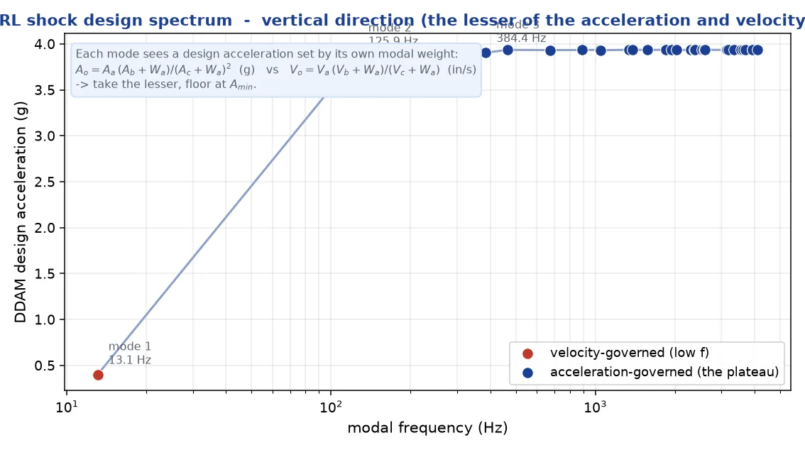
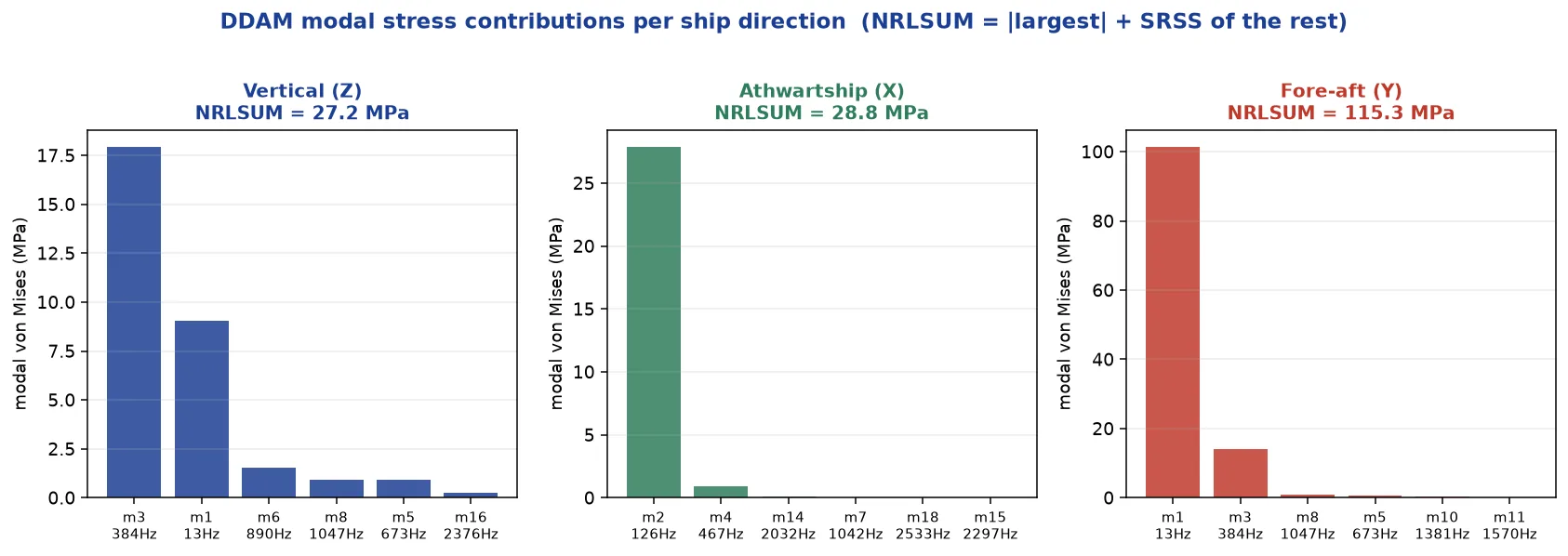
Second, the modes combine by NRLSUM, not SRSS. The NRL sum takes the single largest modal response at its full value and adds the square-root-sum-of-squares of all the others. It is deliberately more conservative than a plain SRSS — shock is not the place to assume the peaks won't line up. Third, there are three ship directions — vertical, athwartship (side to side), fore–aft — each with its own coefficients, and the three results are combined for the resultant.
The model, and what the modes said
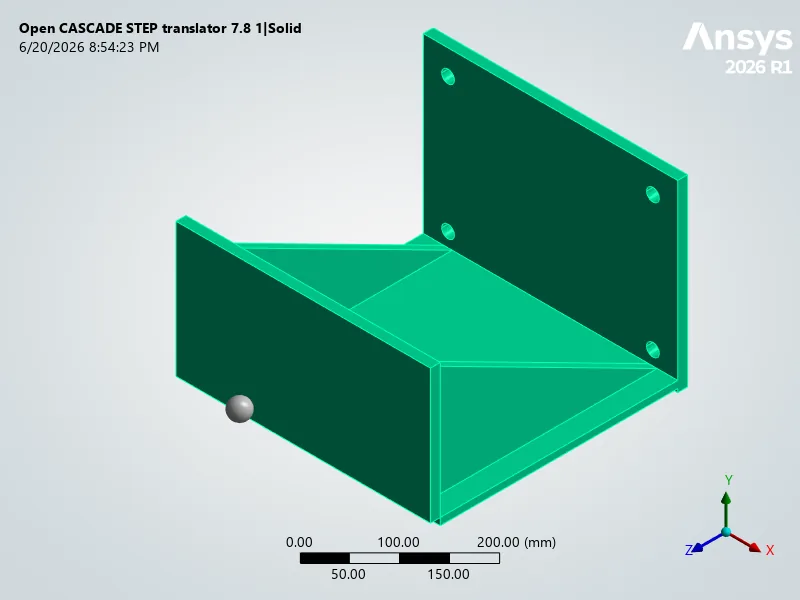
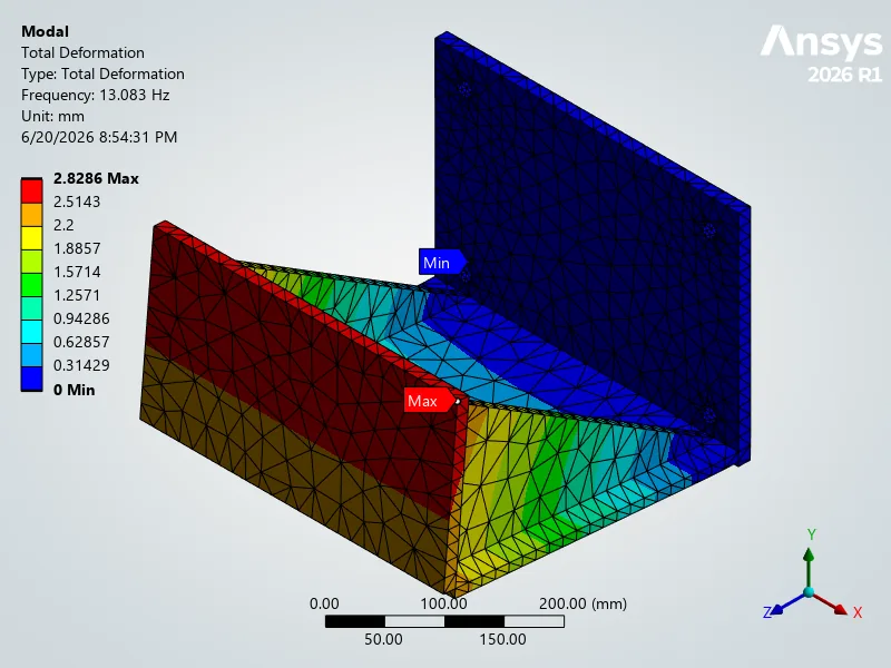
Our bracket is the kind of thing you'd find by the hundred on any warship: a base plate bolted to a deck, a back wall, and a cantilevered shelf braced by two gussets, carrying a 90 kg electronics box. We meshed it, hung the enclosure on as a rigid point mass at its center of gravity, fixed the four bolt holes, and ran a fixed-base modal analysis. Two modes matter, and they tell the whole story before any shock is applied:
- A 13 Hz mode — the enclosure swinging fore–aft on the end of the cantilever. It mobilizes 82% of the fore–aft mass. This is the soft, heavy mode, and it is going to govern.
- A 126 Hz mode — the enclosure swaying athwartship, mobilizing 81% of the athwartship mass. Stiffer, because the gussets brace that direction.
Everything else is above 380 Hz — stiff plate and gusset motion that barely moves any mass. That a soft 13 Hz fore–aft mode exists, and that the NRL coefficients amplify the fore–aft shock the most (Af = 1.0), is the entire reason fore–aft ends up governing.
The shock, applied
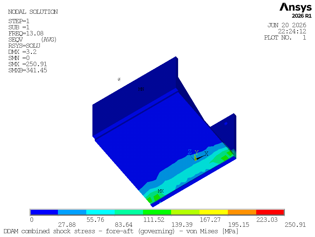
With the modes in hand, the rest is the method turning the crank. For each direction the solver computes every mode's design value, projects it through that mode's participation factor into a mode coefficient, scales the mode-shape stress by it, and NRL-sums across modes. Then the three directions combine. The numbers:
The verdict
The elastic acceptance check is simple: the combined shock stress has to stay under the material yield. Our bracket sees 122 MPa against an HSLA-80 yield of 550 MPa — a ratio of 0.22, a 351% margin. It passes comfortably, and it passes for a reason you can read straight off the modes: it is a stout, gusseted little foundation, and even its softest mode keeps the shock stress to a fraction of yield.
Why this one matters
You can watch the real thing: the Navy's own footage of the USS Gerald R. Ford completing its full ship shock trials — a wall of ocean erupting next to a 100,000-ton carrier, three times, and the ship steaming on. That trial is the spectacular, expensive end of a discipline that mostly happens quietly, in analysis, one bracket at a time. DDAM is how the Navy extends the confidence earned by a shock trial to the thousands of equipment foundations that will never get towed out to a charge of their own. It is unglamorous, decades-old, and absolutely load-bearing: get it right in simulation and a sailor's radar still works after the deck stops ringing.
DDASPEC,1,SURF,HULL,ELAS) on a
representative bracket — it is not a NAVSEA-certified shock qualification. The model and modal analysis ran in
Ansys Mechanical; the DDAM design spectrum, NRLSUM, and three-direction combination ran in MAPDL, with every number
re-derived independently so the combination is fully traceable. A certified analysis uses the contract-specified coefficient set, the
real foundation impedance and fixture details, and the inelastic (elastic-plastic) design values where the method permits.
References: NRL Report 1396; NAVSEA 0908-LP-000-3010; T9070-AJ-DPC-120/3010.Is there a bracket on your ship that has to survive a near-miss it will never be tested against? Ansys
Mechanical solving the modes that matter — the 13 Hz fore–aft sway carrying 82% of the mass —
and MAPDL loading the published NRL coefficients through DDASPEC, NRL-summing each direction and
combining all three, every number re-derived independently so the 122 MPa-against-550 MPa verdict is fully
traceable — is how simulation proves a foundation can take the Navy's shock before anyone sets off a
40,000-pound charge next to a ship. That's innovation through insight.