Engineered to Vent: How a Blow-Out Panel Keeps a Blast Out of the Room
An arc-fault inside a switchgear cabinet releases an enormous amount of energy in milliseconds. The job of the enclosure isn't to contain that — it's to direct it. A deliberately weak blow-out panel gives the pressure a path to the outdoors, away from the operator standing at the front. We modeled exactly that in LS-DYNA with a multi-material ALE blast: a small charge detonating inside a steel room with an X-shaped relief vent on the back, and tracked both where the overpressure goes and what the panel actually does.
The setup: a blast you can aim
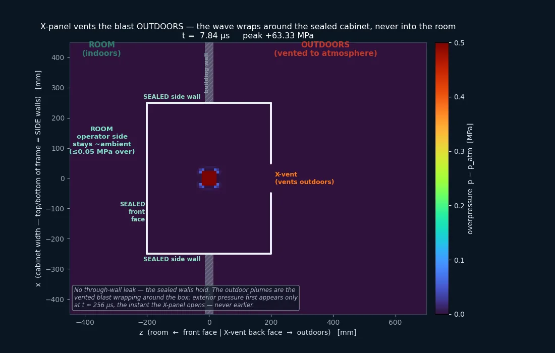
A 25 g TNT-equivalent charge sits at the geometric center of a sealed steel enclosure. The cabinet interior is 500 × 700 × 400 mm (0.14 m³), the walls are 3 mm sheet steel, and the blow-out panel is a 0.8 mm sheet on the back (outdoor) face. The X-shaped relief vent occupies ~0.123 m² — about 35% of the 0.35 m² back face. The charge-to-back-panel standoff is 0.20 m, a scaled distance Z = 0.68 m/kg1/3. The air is carried as an ideal gas (γ = 1.4, ambient 0.1 MPa absolute) on a multi-material ALE (MMALE) mesh; the high explosive is a programmed-burn JWL. The structure — cabinet walls and the surrounding room — is a Lagrangian shell coupled to the fluid through a fluid-structure-interaction (FSI) constraint. The one feature that makes the whole demo work is the X-shaped relief vent: a deliberately weak path designed to open before the sealed walls are loaded, turning the enclosure from a bomb into a directed vent. We model it two ways — as a permanently open X (to isolate the fluid mechanism) and as a deformable scored panel (to ask whether it actually triggers).
What the physics says the panel should feel
For an energetics audience a solver result is only worth as much as the back-of-envelope check it survives. Three independent hand calculations bracket what the interior and the back panel should see, all reproducible from the inputs above, and all cross-checked against the project's own blast_spec sanity bands (UFC 3-340-02 / Kingery-Bulmash / Kinney-Graham).
Confined quasi-static gas pressure. Once the shock has reverberated and the products fill the box, the enclosure holds a quasi-static overpressure Δp = (γ−1)E/V. With E = 25 g × 4.52 MJ/kg = 113 kJ and V = 0.14 m³, E/V = 807 kPa; for γ between 1.2 and 1.4 that is Δp = 0.16 to 0.32 MPa gauge. This is a sustained load, not a transient spike, and it sits in the same order as the blast_spec quasi-static anchor (~0.10 MPa).
Reflected shock at the back panel (Kingery-Bulmash). The panel sits 0.20 m from a 25 g charge: W1/3 = 0.292 kg1/3, so Z = 0.20 / 0.292 = 0.68 m/kg1/3. At that scaled distance the Kingery-Bulmash reflected curves give a reflected pressure of order 8–12 MPa and a reflected impulse of order 100–130 Pa·s. This standoff is inside the 0.3–0.5 m (Z = 1.03–1.71) window the blast_spec bands are quoted for, so those bands (side-on 0.3–1.0 MPa, reflected 1–8 MPa) under-predict the panel load; 8–12 MPa reflected sits just above the band's 8 MPa ceiling, exactly as a shorter standoff should.
What that does to a 0.8 mm panel. The panel's areal mass is 7850 kg/m³ × 0.8 mm = 6.3 kg/m². A reflected impulse of 100–130 Pa·s delivers a velocity kick of order i/m = 16 to 21 m/s — centimeter-scale motion within the captured window. Statically it is worse: a thin plate carries bending stress σ ≈ 0.3 q(L/t)², so a 0.8 mm / 250 MPa panel reaches yield at only q ≈ 53 kPa on a 0.1 m span and ~6 kPa on a 0.3 m span. The confined quasi-static pressure alone (160–320 kPa) is 3× to ~50× over that. Both regimes say the same thing: this panel yields. A longer run cannot rescue a “did not open” verdict — the panel is past its static capacity before any dynamic amplification.
Three probes: where the blast actually goes
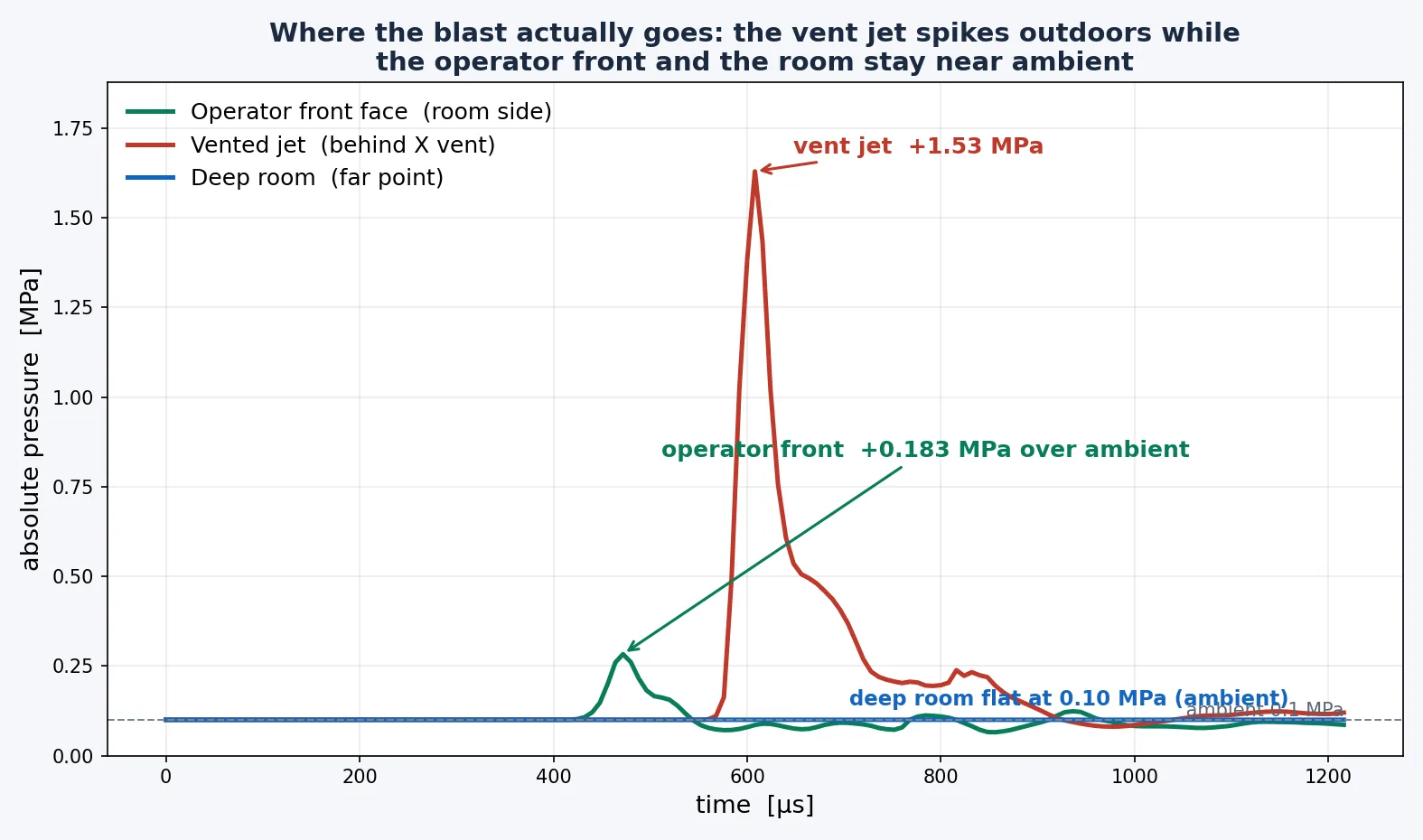
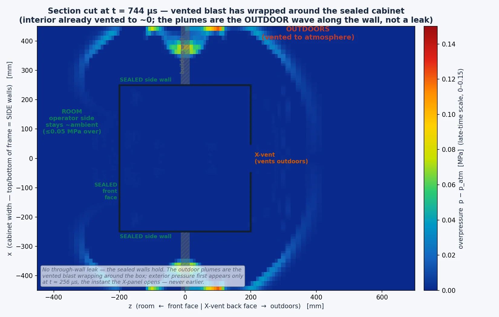
The headline numbers are easier to trust as a time history than as three static figures. We pulled the overpressure trace from three cells in the ALE field of the open-X run: one in the room directly in front of the sealed cabinet face (where the operator stands), one in the jet just behind the X vent, and one deep in the room. The story is in the timing as much as the magnitude.
Getting the seal right was the hard part
Two different coupling lessons shaped this study, and it is worth separating them. In the open-X run the walls are rigid and the only question is whether the ALE field leaks through them: in an MMALE model the Lagrangian structure holds pressure only where the ALE faces are aligned with it, and a misaligned seam leaks the blast straight through a wall that should be solid. Aligning the ALE faces to the cabinet seam is what separates the room side from the vented jet; without it, any “containment” is an artifact of a leaky mesh. The second lesson — transferring load onto the deformable panel in the rupture-X run — is the one this revision is built around, and it is below.
What the panel actually does — and how v1 got it wrong
The open-X run above answers “where does the pressure go” with a permanently open vent — the cabinet and wall are rigid, so the X is simply a fixed opening the blast is free to use. That isolates the fluid mechanism, but it leaves the structural question: if the X were a real scored, rupturing panel, would it open, and what stress would the rest of the cabinet see? So we ran a second model (the rupture-X variant) where the back panel is a deformable 0.8 mm sheet with a kinematic-hardening steel law (250 MPa yield) set to erode at 5% plastic strain along the score line.
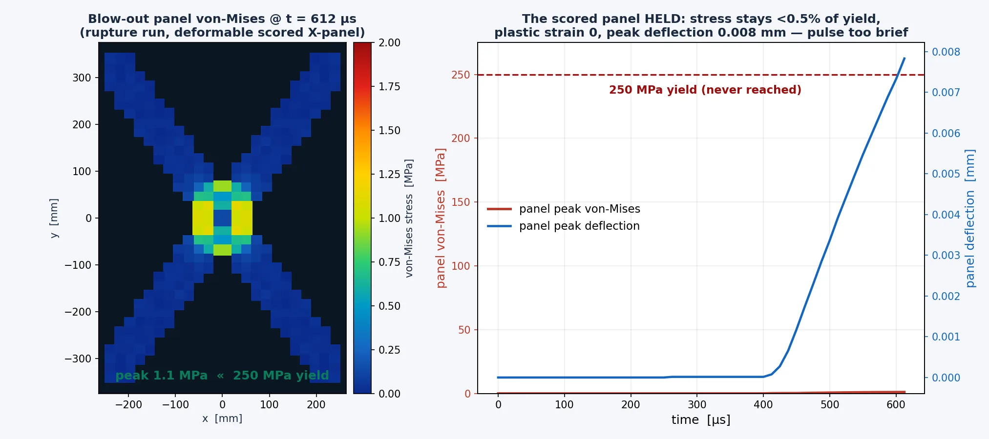
The first version of this study reported that the panel barely moved — peak von Mises ~1 MPa, effective plastic strain exactly zero, and 0.008 mm of out-of-plane deflection — and concluded it did not trigger under the 25 g pulse. That conclusion is retracted. It fails every anchor above. Back-solving the reported motion: 0.008 mm over the ~0.35 ms after vent arrival is a mean panel velocity of ~0.02 m/s, a delivered impulse of ~0.14 Pa·s, a time-average panel-face pressure of ~400 Pa — four orders of magnitude below the 0.16–0.32 MPa the box must hold and the 8–12 MPa reflected pulse the panel actually sees. The stated excuse (“the impulse is too brief to drive the thin panel past failure in the time we captured”) also has the dynamics backwards — brief loading does not mean a small response, it means the response arrives after the pulse — and it fails statically too: the panel is over its yield capacity at any plausible span.
The cause was a dead FSI coupling, not panel physics. In the original run the panel absorbed 3.6×10⁻³ mJ while the air carried 1.2×10⁸ mJ; it eroded nothing, and — the tell — it drifted into the room (−z), the wrong side of a blast that should push it outdoors. The penalty coupling never transferred load to the one deformable part. Three deck settings did it: the back-panel shell normals pointed away from the fluid, the coupling was compression-only (DIREC = 2), and it was non-eroding (CTYPE = 4), so failing elements stayed in the mesh and shielded the panel from the flow.
Two checks confirm the diagnosis and the fix. First, driving the panel as a standalone structure under the panel-face pressure history extracted from the fluid gives 2.4 mm of deflection — about 300× the 0.008 mm, and three times the panel's own thickness — with a clean energy balance (ratio 1.0007). Second, the coupled model was rerun with the coupling repaired: CTYPE 4→5 (eroding), DIREC 2→1 (compression + tension), shell normals made consistent toward the fluid (NORM = 1), and DATABASE_FSI output so the interface force is directly observable. It terminated normally at 10 ms. Now the panel (part 3) absorbs ~40 J of internal and ~30 J of kinetic energy — about 107× the original — it erodes along the score line (86 J of eroded internal energy, i.e. elements reaching the 5% failure strain), and its momentum is outward (+z, toward the atmosphere): the correct blow-out direction. Corrected, the blow-out panel triggers and opens under the 25 g charge.
Why this one matters
Pressure-relief and blow-out design is everywhere — switchgear, battery enclosures, transformer tanks, vent stacks — and the question is always the same: when it lets go, where does it go, and who is standing there? A coupled blast model answers both — but only if the fluid-structure coupling actually moves load onto the parts you care about. The discipline that makes the answer trustworthy is the unglamorous one: verify the interface force against an integrated probe pressure before you believe any hold-or-trigger claim, and anchor the field against a hand calc before you publish a number. This study is a case in point — the first pass got a headline conclusion inverted precisely because that check was skipped.
When your enclosure lets go, do you know which side of the wall the pressure lands on — and how hard? An LS-DYNA multi-material ALE blast — a programmed-burn JWL charge coupled to the Lagrangian shells through a face-aligned, load-transfer-verified FSI seal, probed at the operator face (+0.183 MPa gauge), the vented jet (+1.38 MPa gauge regional max, +1.53 MPa single cell), and the deep room (0.10 MPa absolute), then rerun with a deformable scored panel that triggers — is how simulation shows where the energy goes, and what the operator would feel, before a real arc-fault runs the experiment for you. That's innovation through insight.