Why Pipelines Zig-Zag: The Hidden Flexibility in a Bend
Everyone has seen them — the pipelines that suddenly fold into a big square U or a zig-zag loop before carrying on straight: the expansion loops bristling off a refinery rack, the Trans-Alaska pipeline's famous sideways jogs across the tundra. They look like a mistake, a plumber who lost the thread. They are the exact opposite — deliberate slack, engineered in so the line can grow when it heats up without tearing its anchors apart. Steel stretches about 12 microns per meter per °C; heat a 6-meter run by 280 °C and it grows ~21 mm — and if both ends are pinned, that 21 mm has to go somewhere. Where it goes, and whether the pipe survives the trip, is the science of pipe flexibility, codified in ASME B31.3. We ran the textbook case and watched a humble elbow quietly save the day.
The problem: a line that has to grow
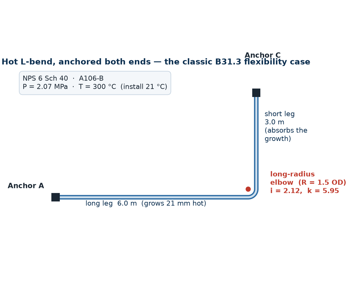
Our line is the kind you'd find on any process unit: NPS-6, Schedule 40, ASTM A106 Gr. B carbon steel, carrying a hot fluid at 300 °C under a representative design pressure of about 4 MPa (~40 bar). It runs 6 m, turns 90° through an elbow, and runs another 3 m to a second anchor. Both far ends are pinned. When the unit fires up, the long leg expands ~21 mm toward the corner, and since it can't push the anchor, the bend has to swallow the motion. The question B31.3 forces you to answer is simple to ask and easy to get wrong: does the layout have enough flexibility to take that growth, or does it stress itself to failure every time it heats up?
Two stresses, two different fears
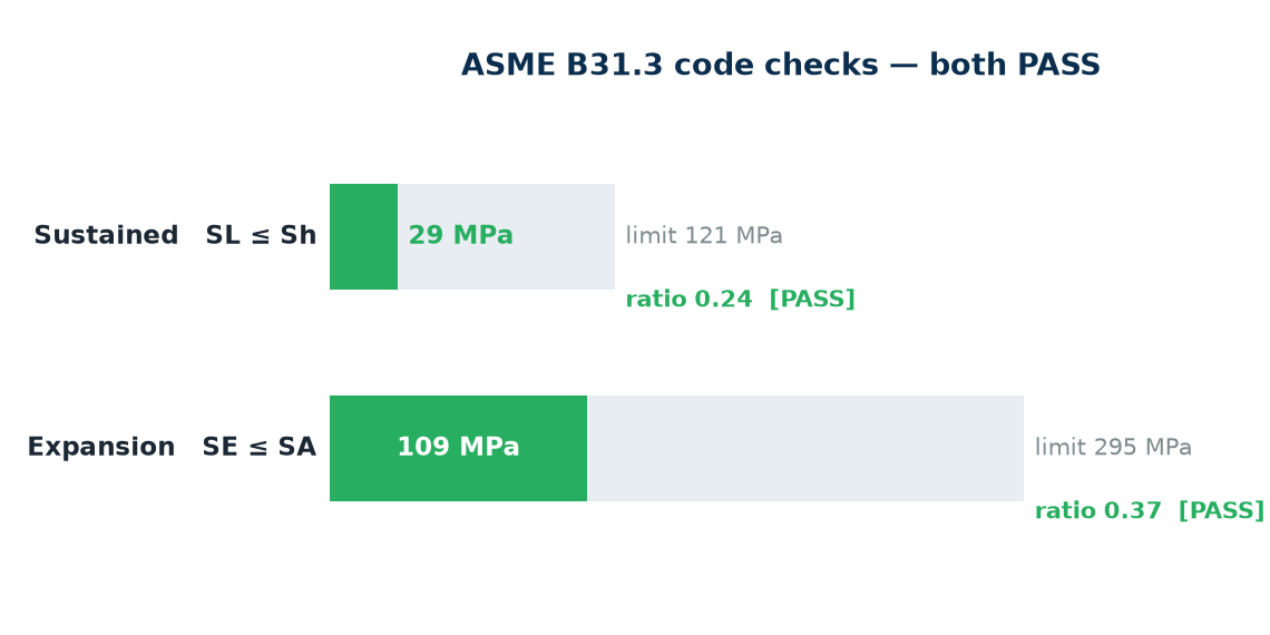
The code is careful here, and the carefulness is the whole point. It cares about two stress categories, and they are not the same physics. The first is sustained longitudinal stress — pressure plus the dead weight of pipe and fluid — which must stay under the hot allowable Sh. That check is about not collapsing: a load that sits on the pipe all day, every day, and must never exceed what the material can hold at temperature. The second is the displacement stress range from thermal expansion, which must stay under SA. That one is about fatigue — the line heats up, stretches, cools, relaxes, and does it again every startup and shutdown. It is a range, not a peak, because the damage is in the cycling. Different limit, different fear, different physics — and the expansion range is where this layout lives or dies.
A straight pipe fights bending. A curved elbow ovalizes — and that is exactly what saves the line.
The hand calc says: reject it
The classic way to size this by hand is the guided cantilever. You treat the short leg as a beam, fix one end, and force the other through the full 21 mm of growth, then read off the bending stress. It is fast, conservative, and on this layout it returns a verdict you don't want: a displacement-stress range of SE = 500 MPa against an allowable SA ≈ 295 MPa — a ratio of 1.69. On paper, the design fails. Send it back, lengthen a leg, add a loop. Except the hand method is hiding something, and that something is the elbow.
The twist: an elbow is a hinge in disguise
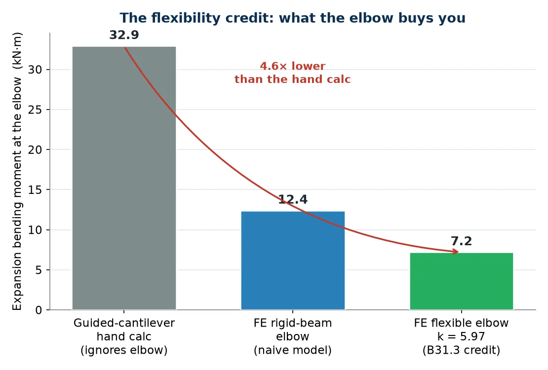
Here is the piece the guided cantilever throws away. A straight pipe is stiff in bending — its round cross-section holds its shape, so it resists like a solid beam. A curved elbow does something a straight pipe cannot: under a bending moment its circular cross-section squashes slightly oval. That ovalization is a release valve. As the section flattens, the elbow gives way far more easily than its dimensions suggest — it acts as a flexible hinge, here about 6 times more flexible than a straight pipe of the same length. B31.3 calls that the flexibility factor, and for this elbow k = 5.95. That hinge is precisely what relieves the thermal moment: the elbow folds a little instead of forcing the whole bend to fight the growth. The hand method, which models the run as straight beams, never sees it.
The same ovalization cuts both ways, and the code makes you respect both edges. Flattening the section adds flexibility — but it also concentrates stress at the elbow, so B31.3 pairs the flexibility factor with a stress-intensification factor, here i = 2.12. Both are set by a single geometric number — the elbow’s flexibility characteristic h = tR/r2 ≈ 0.28 for this long-radius elbow — through the code’s own relations k = 1.65/h and i = 0.9/h2/3, so the two are not independent numbers but two readings of the same ovalization. Flexibility and stress-intensification are two faces of the same ovalization coin: the bend bends more easily, and it pays for that ease with a local stress multiplier you are not allowed to ignore.
The flexibility analysis
To capture the hinge honestly, we built the L as a pipe-element frame in Ansys — PIPE289 straight elements for the two legs, with the curved run given its B31.3 flexibility credit so the elbow ovalizes the way the code says it does. Then we let the long leg grow and read the moment the bend actually has to carry. The result is the headline of the whole study: the true expansion moment comes in 4.6× lower than the guided-cantilever bound. The hinge does real work.
The verdict
With the elbow's real flexibility credited, the numbers turn over completely. The displacement stress range that the hand calc put at 500 MPa drops to SE = 109 MPa. And the sustained check — the don't-collapse one — passes with room to spare.
Why the zig-zags exist
Tie it back to the refinery rack and the Alaskan tundra. This study is the same story those loops tell. When the legs of a run are long enough and the bends are flexible enough, a layout flexes on its own — as ours did, the elbow quietly absorbing 21 mm of growth. But when the legs are too short or too straight to flex enough, the moment has nowhere to go and the anchors take the punishment. So engineers add an expansion loop: a deliberate square U or zig-zag that buys more of exactly the flexibility we just credited — more elbows, more hinge, more give. The bend you see from the highway isn't a detour around an obstacle. It's the design absorbing the heat, one ovalizing elbow at a time.
Why this one matters
Pipe flexibility is one of those disciplines that looks like overcaution until you watch what it prevents. The hand calc isn't wrong — it's conservative, and conservatism that rejects a perfectly good layout costs real money in steel and loops that were never needed. The rigorous analysis isn't about cutting corners; it's about understanding the structure well enough to credit the flexibility that is genuinely there. An elbow ovalizes whether or not your hand calc admits it. Model that honestly and the same humble bend that looked like a failure becomes the thing that saves the line — and you stop paying for slack the physics already gave you for free.
Did a conservative hand calc just condemn a piping layout you suspect is actually fine? A PIPE289 pipe-element frame in Ansys, crediting the elbow its full B31.3 flexibility — cutting the expansion moment 4.6× below the guided-cantilever bound, dropping the displacement stress range from a failing 500 MPa to SE = 109 MPa against SA = 295, and clearing the sustained check at SL = 29 against Sh = 121 — is how simulation rescues a sound design before you pay for steel and expansion loops the physics never required. That's innovation through insight.