The Code That Keeps Boilers From Exploding: Design-by-Analysis of a Nozzle Junction
A pressure vessel is a bomb that's allowed to exist because someone proved it won't go off. The proof has a name — the ASME Boiler & Pressure Vessel Code — and Section VIII Division 2, Part 5, is the part that lets you replace a handwritten formula with a finite-element model. We pointed Ansys Mechanical at the single hardest spot on a real vessel — where a nozzle is welded into the shell — and ran it through the core Part 5 gauntlet: linearize the stress, classify it, and check every number against a code clause.
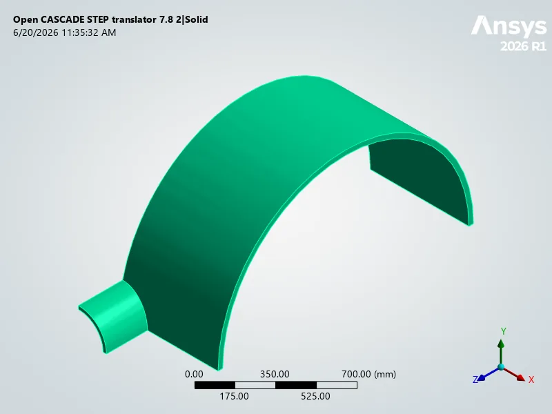
The problem: a hole in a pressure vessel
Put a hole in something that holds pressure and you've created a stress concentration; weld a pipe into that hole and you've created the worst one on the whole vessel. The shell wants to balloon, the nozzle resists, and the weld at the junction takes the argument. Run a linear-elastic solve and the peak von Mises stress at that weld comes out at 270.8 MPa — well above the material's allowable. Naively, you'd fail the vessel and thicken the wall.
That naive read is wrong, and understanding why is the entire point of design-by-analysis. The 270.8 MPa is a local peak at a geometric discontinuity. It doesn't represent a load the wall has to carry across its whole thickness — it's a spike at the surface that a tiny amount of local yielding relaxes without the vessel caring. Comparing that raw peak to an allowable is comparing the wrong two numbers.
The peak stress at a weld is not a failure. Treating it like one is how you over-build a vessel — or miss the failure that actually matters.
The method: linearize, then classify
The genuinely clever idea at the heart of VIII-2 is stress linearization. Instead of reading the peak, you draw a line straight through the wall — a Stress Classification Line — and split the stress distribution along it into three parts: a constant membrane stress (the average that the whole thickness carries), a linear bending stress (the part that varies from inside to outside face), and the nonlinear peak (the surface spike that's left over). Each part fails the wall in a different way, so each gets its own name and its own allowable.
- Pm — general primary membrane. Pure pressure tension; if this exceeds the allowable the wall ruptures. Checked against S.
- PL — local primary membrane near the discontinuity. Allowed to run higher because it's local. Checked against 1.5S.
- PL+Pb — membrane plus bending through the wall. Checked against 1.5S.
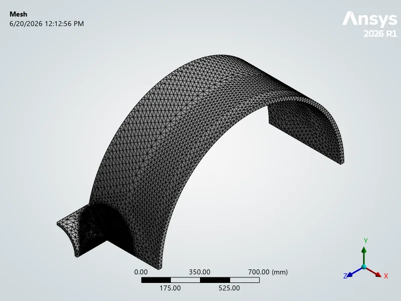
The hard engineering — the part that separates a vessel engineer from a colorful picture — is deciding where to draw the classification lines and how to categorize what they read. We ran three: through the shell crotch at the junction, through the nozzle neck, and through a far-field stretch of shell to capture the clean membrane stress away from any disturbance.
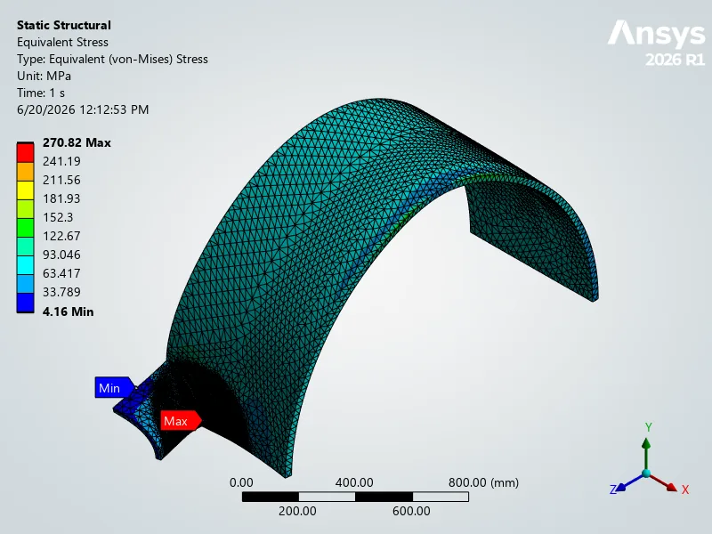
Linearized, the same field that read 270.8 MPa at the weld tells a completely different and far more useful story. The far-field membrane is 71 MPa — comfortably under the allowable. That 71 MPa is the von-Mises equivalent membrane, which is the quantity VIII-2 classifies against; the basic hand-calc hoop stress, P·R/t = 3.0·764/28 ≈ 82 MPa, is the largest single component behind it, and the two are consistent for a closed cylinder carrying biaxial pressure tension. The local membrane at the crotch is 168 MPa, and the membrane plus bending through the wall is 201 MPa — both well under their 1.5S limit of 276 MPa. The 270.8 MPa peak was real, but it was the part you're allowed to have.
The second opinion: let the steel yield
Linearization is the classic route, but VIII-2 offers a modern complement that's arguably more honest: elastic-plastic analysis. Instead of arguing about how to categorize an elastic stress, you give the steel its real ability to yield — an elastic-perfectly-plastic stress-strain curve — and ask the solver whether a stable equilibrium exists. Run it first at the design pressure, just for the physical picture: does the junction actually yield, and if so, how much?
Barely. At the design pressure the junction peak just nudges past yield, a small, confined plastic zone forms at the weld, and the surrounding elastic material picks up the slack — the stress redistributes. This is exactly the physical mechanism that makes the 270.8 MPa elastic peak harmless: a thimbleful of local yielding, nowhere near gross plastic collapse.
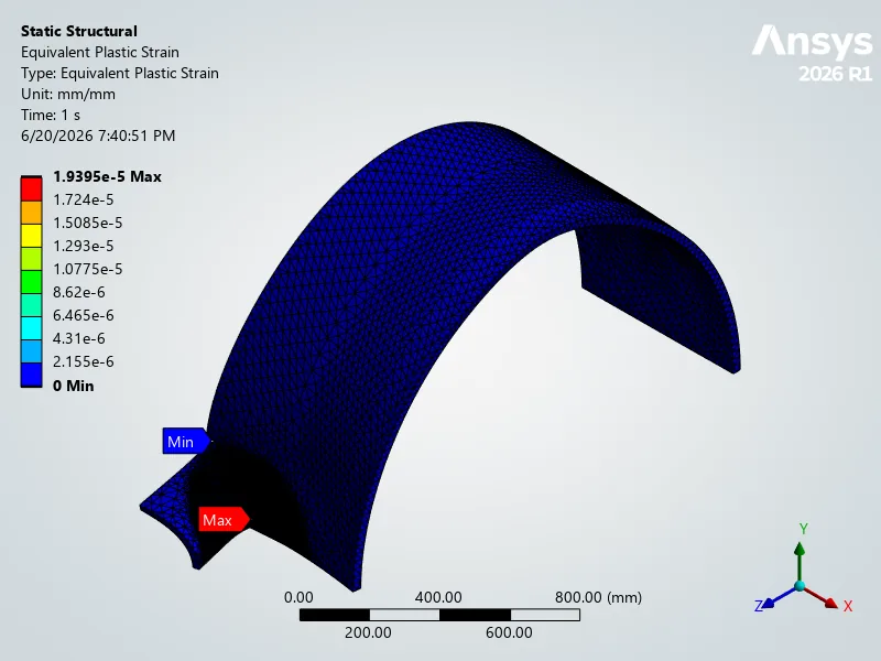
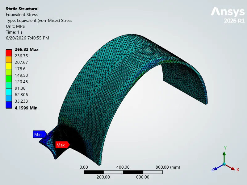
That design-load picture is the intuition — it is not the code check. Clause 5.2.3, protection against plastic collapse, is stricter and specific: it asks for a converged solution under the factored load combination — 1.5× the design pressure (4.5 MPa here) — with the yield raised to 1.5S = 276 MPa and small-displacement theory, so no geometric stiffening is allowed to flatter the result. We re-ran it exactly that way. The solve converges all the way to the full factored load, an achieved load factor of 1.50, and that convergence is the pass: the plastic limit load exceeds 1.5× the design load. At the factored load the peak von Mises reaches 282 MPa in the local plastic zone — right at the 276 MPa yield — and the equivalent plastic strain tops out at just 0.08%, with under 2% of the vessel yielding at all: confined plasticity at the crotch that redistributes to a new stable equilibrium, a wide margin from gross collapse.
The scorecard
The whole assessment collapses to one table: each failure mode, the clause that governs it, the FEA number, and the allowable it has to clear.
Five checks, five clauses, five passes — and a raw peak stress that, read naively, would have sent you back to thicken a wall that never needed it. That gap between the naive read and the code-correct read is the entire value of design-by-analysis.
Why this one matters
The wine glass and the slinky are the fun demos. This is the one the world actually runs on. Every boiler, every refinery column, every reactor, every hydrogen tank carries a stamp that says someone proved it safe — and increasingly that proof is exactly this: not a single colorful stress plot, but a disciplined translation of a finite- element field into the categories the code understands, each one checked against a clause, each clause traceable to a failure mode. ASME VIII-2 Part 5 is the rulebook that turns "the stress looks high at the weld" into "the vessel is safe, and here's the line-by-line reason why." Get that discipline right in simulation and you can clear a junction design long before anyone strikes an arc.
Staring at a peak stress at a nozzle weld that blows past the allowable? Ansys Mechanical working this junction through the VIII-2 Part 5 discipline — linearizing the elastic field along three stress classification lines to hold Pm, PL, and PL+Pb under their S and 1.5S allowables, then converging an elastic-perfectly-plastic limit-load solve to the full 1.5× factored load that shows the 270.8 MPa peak relaxing into a small confined plastic zone, five code checks passed out of five — is how simulation separates a harmless surface spike from a real failure before you thicken a wall that never needed it. That's innovation through insight.