Can the Arthur Ravenel Bridge Hold a Boeing 747?
Anyone who has driven over the Arthur Ravenel Jr. Bridge in Charleston, South Carolina — two 575-foot diamond towers holding a 1,546-foot main span over the Cooper River — has probably had the same idle thought at the top of the climb: it’s basically a runway up here. In an emergency, could a jet just put down on it? We took the question seriously and built a real finite-element model of a Ravenel-class bridge in Ansys, then set a fully-loaded Boeing 747 down on the deck. The answer is a genuine split decision, and it is more interesting than a flat “no.”
Really three questions, not one
“Can it land there” hides three separate engineering questions, and they have different answers. Can the structure carry the weight? That is a job for a solver — deck bending, cable tension, tower load. Can the aircraft physically fit? That is geometry: wingspan against roadway width. Can it stop in time? That is a look-up: landing roll against available deck. Only the first needs simulation; the other two the asker rightly pointed out “can just be looked up.” So we solved the hard one and measured the other two honestly.
Building a Ravenel-class bridge in Ansys
We assembled a parametric model to the bridge’s published principal dimensions — a 471 m cable-stayed main span, 200 m back spans, two 175 m towers, a 38.4 m deck carrying eight lanes, and two edge stay planes in a fan of 120 cables. It is exactly the kind of structure the question calls for: beams, shells and cables. The deck is a SHELL181 concrete slab (its reinforcement carried as smeared section stiffness, not modeled bar by bar); the edge girders, transverse floor beams and tower masts are BEAM188 members; the stays are tension-only LINK180 cables. The whole assembly is 4,655 nodes and 2,786 elements — a small model, because a beam-shell-cable frame is efficient and every load case solves in seconds.
This is a representative bridge of the Ravenel’s published geometry, not the confidential as-built design-office model — we do not have its rebar schedules or its cable pretension, and we do not claim to. The 747 enters the model the way the question suggested: as mass, not aircraft. Its published weights are applied through the landing-gear footprint — a nose patch and four main-gear patches spread so the concentrated bogie loads land where they really would. We ran six load cases: the bridge’s own dead weight; the AASHTO HL-93 design live load (the everyday highway loading the deck was actually built for, and our reference); the 747 at maximum landing weight and at the heavier maximum take-off weight; an emergency touchdown (landing weight multiplied by a representative 1.5 dynamic factor — deliberately above the AASHTO highway dynamic load allowance of about 1.33, since a hard set-down is not a gentle park); and the jet positioned beside a tower, where it loads the cables and tower hardest.
One honest note on how the solve ran. On this machine, standard batch Ansys Mechanical APDL has sometimes stamped structural runs “verification only.” We gated against that: a tiny structural probe deck runs first and the job aborts if the license banner appears. It did not — forcing the Mechanical Enterprise product, the full model solved for real, all six load cases, no verification banner. Every number below is read straight off the results file.
Does the structure even feel the jet?
Less than you would guess. The surprise is a matter of arithmetic: a 747 at maximum landing weight is 2.80 MN — about 4 % of the 65 MN of AASHTO design traffic the deck is built to carry spread across its lanes. A jumbo jet feels enormous, but a bridge this size lives under many hundred tons of rush-hour truck loading every day. The catch is that the aircraft’s weight is concentrated, so it punches above its featherweight share: parked at mid-span it deflects the deck about a third as much as a full design-traffic loading does, and the emergency touchdown pushes that to roughly half.
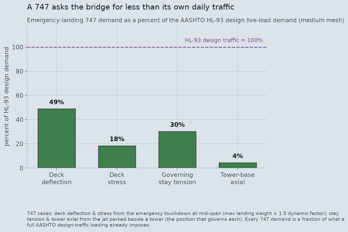
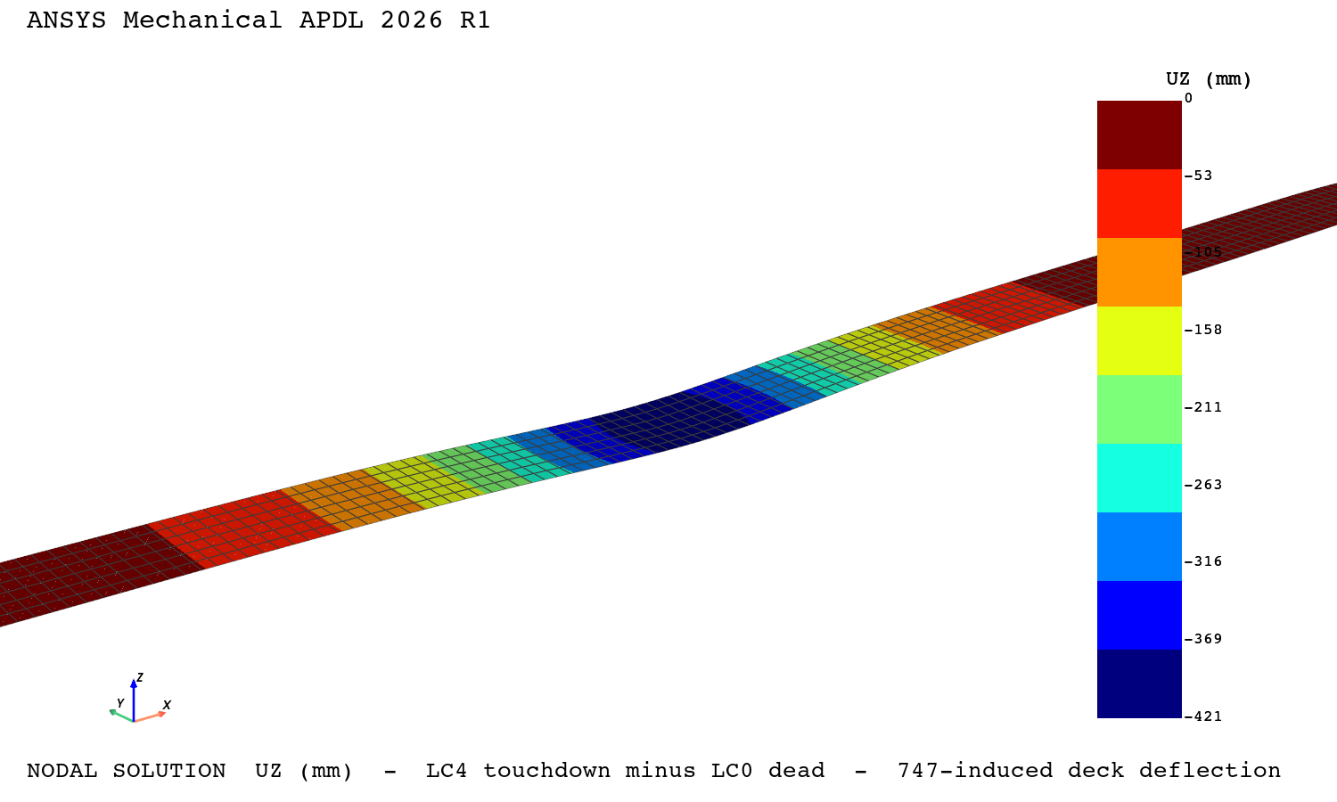
Across all four load paths the story is the same. The worst mid-span deflection the emergency touchdown adds is 0.42 m, against 0.86 m from the design traffic — 49 %. The most-loaded stay, with the jet beside a tower, gains 30 % of the tension a design loading adds. Deck bending stress rises 18 %; the load reaching the tower base, 4 %. Nothing here is close to an overload. If a 747 came down on this bridge and somehow stayed on it, the structure would hold — comfortably.
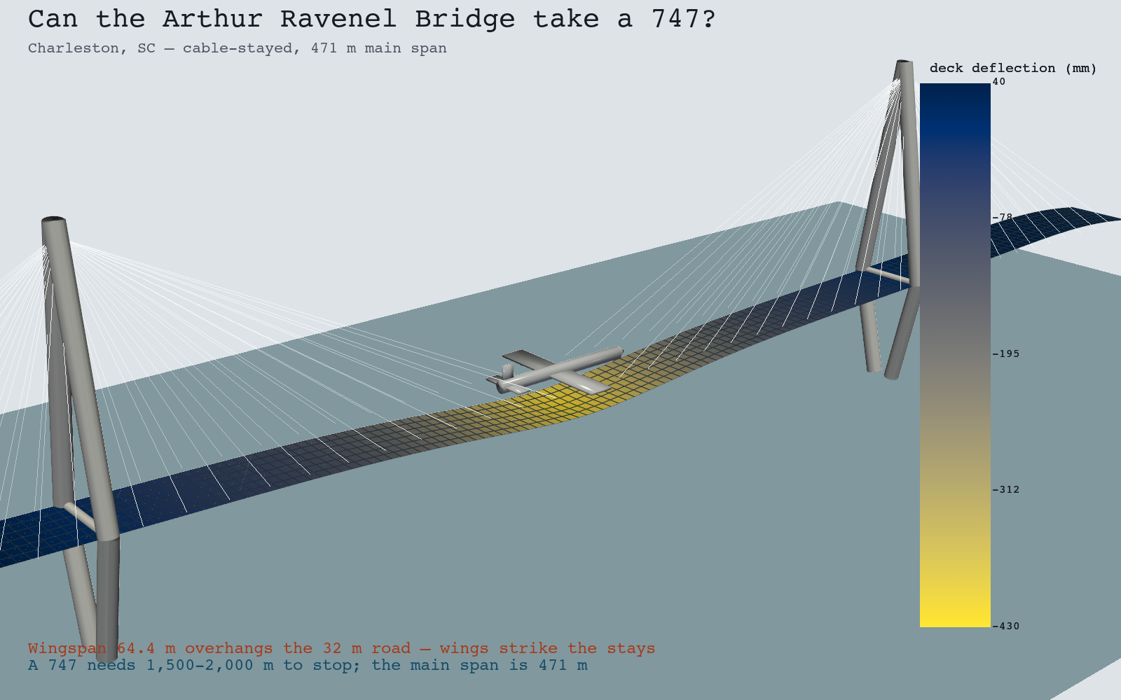
And because it is a real finite-element solve underneath, the Ansys solver draws its own picture of the result — the vertical deflection the emergency landing adds to the deck, read straight from the results file.
Trusting the numbers
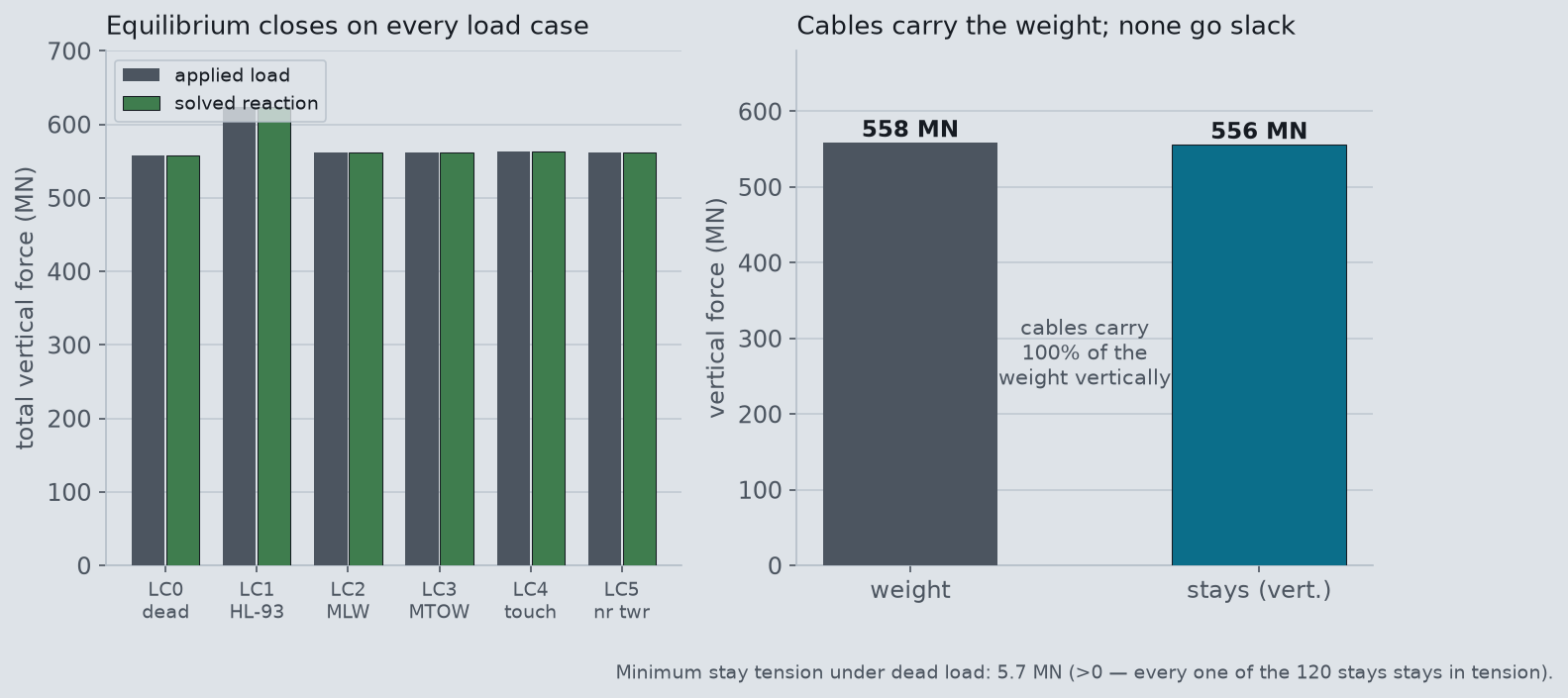
A converged solve that is quietly wrong is the default failure of this kind of work, so before believing any verdict we ran the model through the usual gauntlet. First, equilibrium: the sum of the support reactions has to equal the load applied, on every load case. It does, to better than one percent each time — the aircraft cases return exactly their applied weight (2.80 MN at landing weight, 3.89 MN at take-off weight, 4.20 MN for the factored touchdown). Second, the cables: on a cable-stayed bridge the stays should carry essentially all of the deck’s weight, and none of them should ever go slack. They do exactly that — the vertical components of the 120 stay tensions sum to 556 MN against a 558 MN total weight (about 100 %), and the least-loaded stay still holds 5.7 MN of tension. Every cable stays in tension in every load case, which is what makes the linear model trustworthy for these gravity loads.
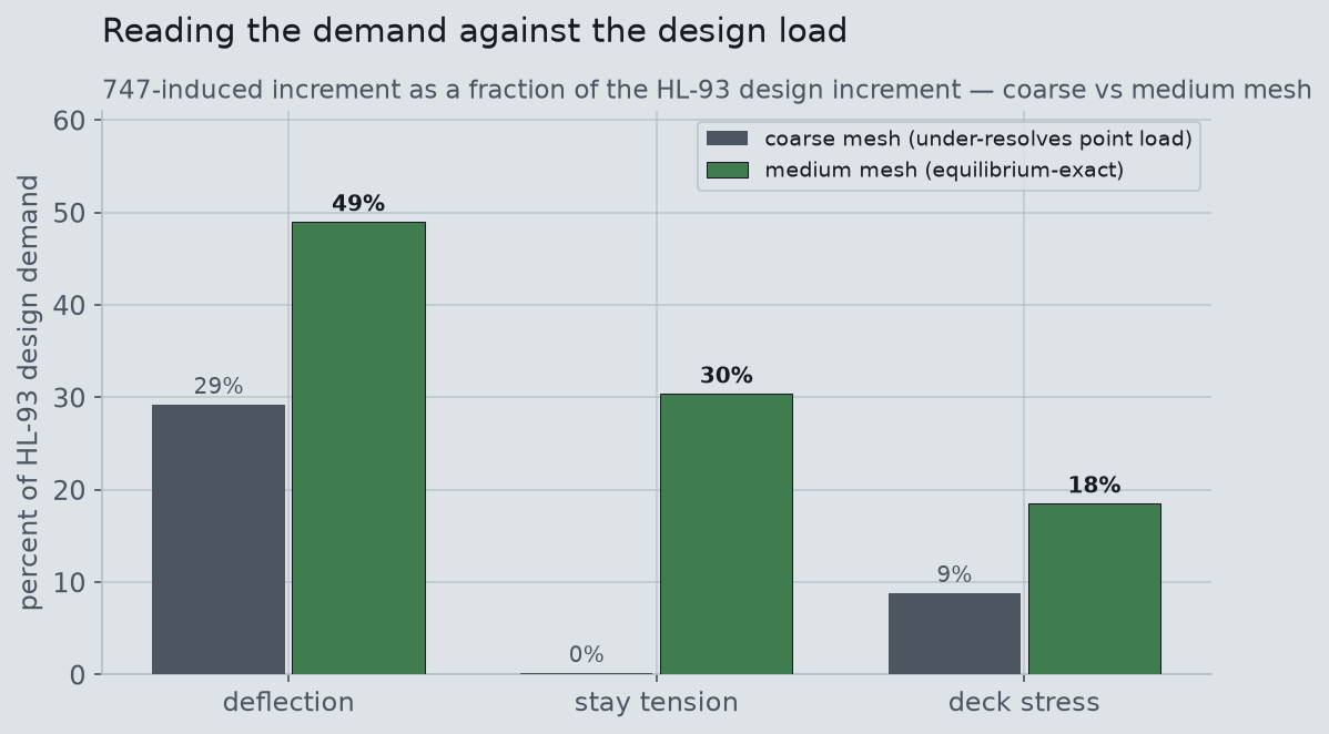
Third, mesh. We solved the bridge twice, at a coarse and a medium deck mesh. The two do not agree tightly — and the reason is itself a useful check. On the coarse grid, the concentrated gear patches fall between deck nodes and part of the aircraft’s load is lost; the equilibrium test catches it red-handed (the coarse mesh returns only 1.5 MN of the 2.80 MN it should). The medium mesh resolves the footprint and balances exactly, which is why every number quoted here is the medium result. A finer mesh is the natural next refinement, and we flag it rather than claim convergence we did not earn.
Finally, a hand-check the global mesh cannot do. A five-meter shell element cannot see a single tire; local deck-plate bending under an individual wheel is a separate calculation. A 747 main-gear bogie is about 666 kN — roughly 166 kN on each of its four tires, about 2.3 times an AASHTO design-truck wheel. A simply-supported deck-strip calculation puts the local plate bending near 12 MPa: demanding, but the kind of wheel load a reinforced bridge deck is designed to shrug off. The concentrated jet stresses the deck locally about as hard as heavy trucks already do, and globally far less.
Strong enough — but you still can’t land there
So the structure wins its argument. The geometry does not, and it loses twice. A 747’s wingspan is 64.4 m; the usable roadway is about 32 m. The wings are twice the width of the road. Each wingtip reaches some 13 m past the edge of the deck — out over the stay cables and open air. There is no version of an approach that threads a wide-body between two planes of cables spaced 38 m apart; the wings hit the stays long before the wheels find the road.
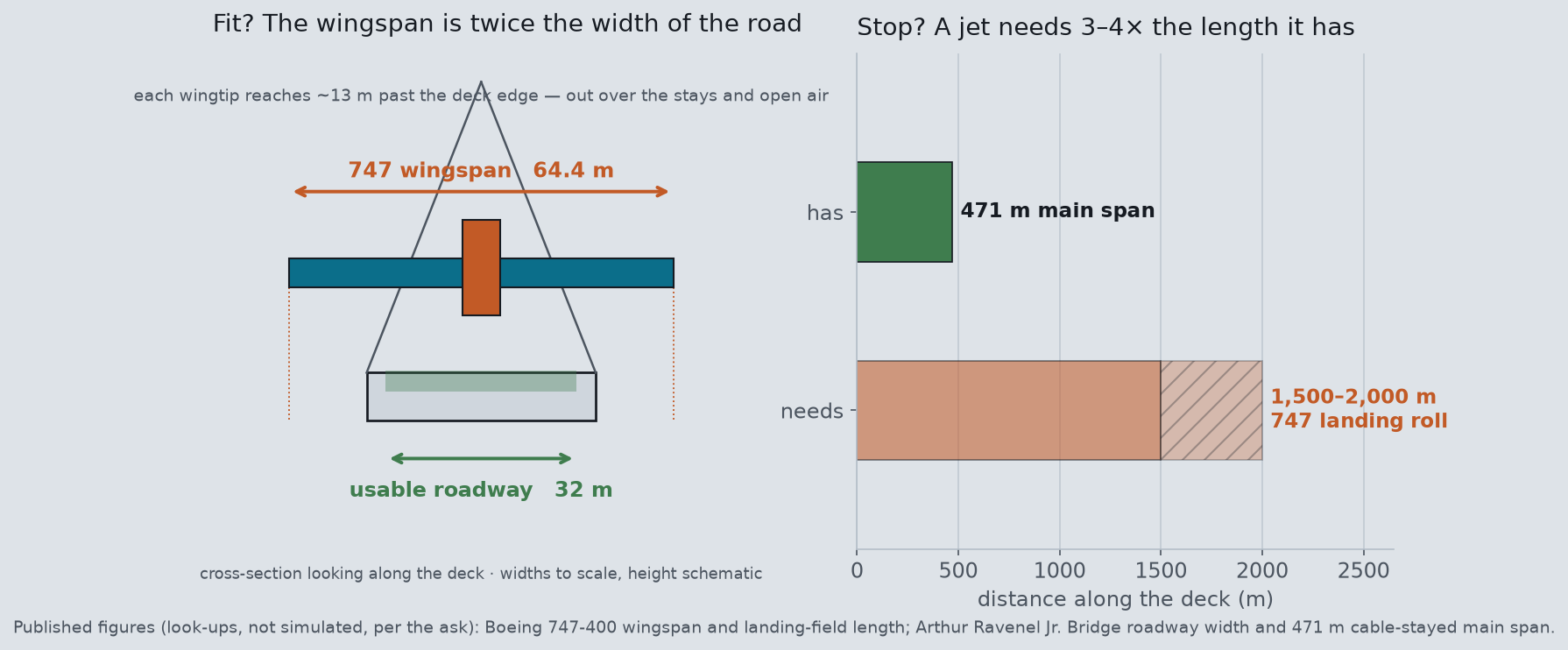
And even if the wings somehow cleared, the jet could not stop. A 747 needs roughly 1,500 to 2,000 m of landing roll. The cable-stayed main span is 471 m; the whole bridge, approaches included, is still only a fraction of what a wide-body needs to shed its speed. The aircraft would run off the far end long before it slowed to a stop. The structure could take the weight of the emergency landing — it simply is not, and was never meant to be, a runway.
Honest scope. This is a representative finite-element model built to the Arthur Ravenel Bridge’s published principal dimensions and representative steel, cable and deck sections — not the confidential as-built design, its rebar schedules or its cable pretension. Reinforcement is carried as smeared section stiffness, not modeled bar by bar. Each diamond tower is idealized as twin masts carrying the same two stay planes; the diamond shape in the hero is drawn for recognizability. The 747 is applied as its published weights through the landing-gear footprint, with a self-authored generic wide-body silhouette for scale — not a licensed Boeing model or an aerodynamic one. The landing is a static load times a representative 1.5 dynamic factor (an assumed allowance set above the AASHTO highway dynamic load allowance of ~1.33, not calibrated to a landing-specific code), not full landing dynamics (tire contact, gear oleo, flare, braking and asymmetric touchdown are not simulated). Local tire punching of the deck plate is reported as a hand-check, not resolved by the global mesh. Cable pretension is omitted; because the model is linear, the 747-induced response we report is independent of it by superposition, and every stay is confirmed in tension. Without pretension the absolute dead-load deck sag is far larger than a real, tuned bridge’s, so we report only the pretension-independent 747-induced increments and their ratios to the design load, never an absolute deflection. We report demand relative to the AASHTO HL-93 design load and to first-yield allowables, not an ultimate collapse load; wind, aeroelastic, soil-foundation, thermal and fatigue effects are outside this study. The coarse mesh under-resolves the concentrated gear load (shown in the equilibrium check); the medium mesh is reported and a finer mesh is the stated next step.
Have a what-if that deserves a real solver instead of a back-of-the-envelope guess? The satisfying answers often come from taking an offhand question and actually meshing it — a structure, a flow, a field — and letting the physics settle the argument. If you are curious whether an Ansys model could pin down something you have always wondered about, we would love to talk it through. Rand Simulation is an Ansys (Synopsys) Apex Channel Partner, and this whole study — geometry, mesh, solve and post-processing — was run end to end by an agentic AI workflow on our own licenses. Innovation Through Insight™.