The Best Armor in Orbit Is a Sheet of Foil Held Out in Front
A 4 mm aluminum sphere traveling at 7 km/s arrives with the kinetic energy of a rifle bullet — about 2.2 kilojoules packed into a peppercorn — and no spacecraft can carry enough armor to stop it head-on. What works instead is 0.8 mm of foil hung 100 mm out in front — thin enough to be nearly free, and in Ansys LS-DYNA it beats 3.8 mm of solid plate of the same total weight. In 12 microseconds the sphere stops being a bullet and becomes a cloud 64 mm across.
The physics: at orbital speed, aluminum stops behaving like metal
Low Earth orbit is not empty. It is stocked with hardware that has come apart — spent upper stages, collision debris, fuel-tank shrapnel. The dangerous part of that population is the middle of it, roughly 1 cm to 10 cm: big enough to end a mission outright, too small to catalog and dodge. Closing speeds average near 10 km/s, more than ten times the muzzle velocity of a rifle. You cannot see these fragments coming and you cannot outrun them, so the only move left is to survive being hit.
The instinct is to add plate, and the instinct is wrong — because armor intuition is calibrated on things that arrive at hundreds of meters per second, not thousands. Aluminum yields at a few hundred megapascals. A 7 km/s impact generates contact pressures in the tens of gigapascals — a hundred times past the strength of the material on either side of the collision. For the first few microseconds, strength is not a relevant property at all: the projectile and whatever it strikes both flow. The metal behaves like a fluid. Adding thickness in that regime does not buy proportional protection; it simply hands a still-concentrated lump more material to bore through.
In 1947 the astronomer Fred Whipple proposed the counterintuitive alternative that every crewed vehicle and long-life satellite now flies. Do not try to stop the fragment. Change its shape while it is still a long way from anything that matters: hang a thin sacrificial bumper in front of the real wall, separated from it by a gap. The bumper stops nothing at all. It shatters the threat early, and the gap gives the pieces room to get away from each other.
Why that helps is worth being precise about, because momentum is conserved: none of it goes away, and the cloud still travels downrange at close to the original speed. What changes is the area it arrives over. Pressure is force divided by area, and damage is a story about pressure, not momentum. Spread the same momentum across a footprint hundreds of times larger and the wall feels a broad shove rather than a focused punch: the difference between being pushed with an open palm and stabbed with a thumbtack. The bumper does not weaken the threat. It de-concentrates it.
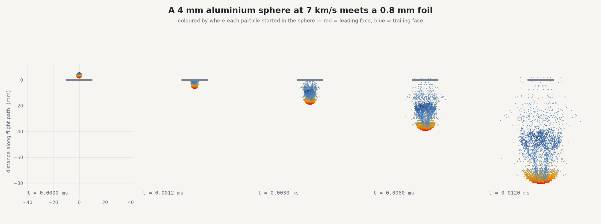
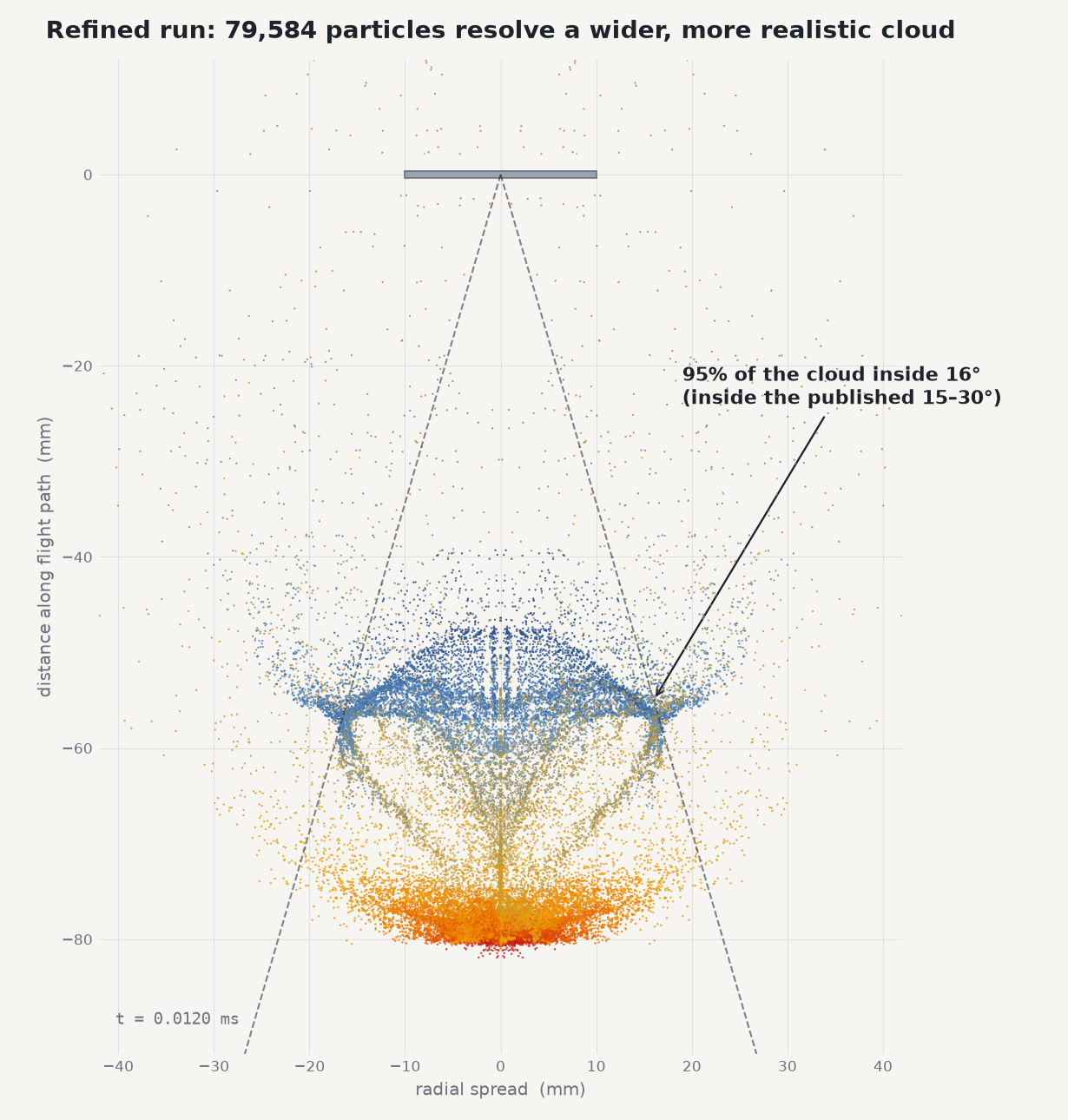
In this model that transformation takes twelve microseconds. A coherent 4 mm sphere — about the size of a peppercorn — becomes a cloud roughly 64 mm across and 82 mm long, the size of a grapefruit, arriving at the rear wall as a diffuse pressure pulse instead of a projectile.
The shape of that cloud is the part most sketches get wrong. It is not a fan; it is a hollow, expanding bubble. Coloring the particles by where they began inside the sphere makes the shattering mechanism visible: the leading face is crushed and stalled the instant it touches the foil, and the body of the sphere overruns it — material driven at 7 km/s into material already brought to a halt. That overrun is what does the shattering.
What the coloring shows after the shatter deserves a more careful sentence than the first version of this article gave it. In this solve, the stalled leading-face material rides compact at the nose of the cloud while the trailing material fans out wider behind it. Flash radiographs of real Whipple debris clouds — Piekutowski’s classic series — show the reverse arrangement: the least-shocked material from the rear surface of the projectile forms the compact front element, while the heavily shocked leading-face material disperses. Our cloud’s internal layering inverts that, so we present it as an observation of this model — plausibly an artifact of how SPH particles load against the Lagrangian foil — not as the mechanism of real clouds. The quantities this study actually rests on (the cone angle, the spread, the footprint at the wall) are bulk measures that do not depend on which face rides where.
Inside the model
The projectile is modeled with smoothed-particle hydrodynamics — a cloud of particles rather than a mesh — because meshless material can genuinely separate, tumble and fly apart as a debris field rather than quietly deleting itself. The bumper and the rear wall are Lagrangian solid elements carrying a Johnson-Cook strength model and a Mie-Grüneisen equation of state, so the shock physics is represented rather than assumed: the equation of state carries the pressure, the strength model carries what little strength still matters at these pressures. The geometry is deliberately generic aluminum-on-aluminum — a 4 mm sphere, a 0.8 mm bumper foil, 100 mm of standoff, a 3 mm rear wall. The reference case tracks 9,843 particles across 82 output frames; the finest resolves the same impact with 79,584 particles at 0.075 mm spacing, putting about eleven particles through the thickness of the foil. Solver: Ansys LS-DYNA, explicit.
Is it right? Check the debris cone against measured clouds
The number a shield designer wants out of this model is not the width of the cloud but its angle, because the angle sets how far apart the bumper and the wall have to be. Resolve the cone and the standoff follows; get the cone wrong and every gap on the drawing is wrong with it.
Quoting a spread angle from the single furthest-flung particle is easy and misleading — one stray fragment sets the whole number. A percentile is the honest measure, so the quantity here is the half-angle containing 95 % of the debris. At the finest resolution that angle is 16.2°, inside the 15–30° band reported for measured Whipple debris clouds — the range published for the real thing, on a quantity nobody tuned it to hit.
It arrives there monotonically. The same impact solved at 0.150, 0.100 and 0.075 mm particle spacing returns cone half-angles of 10.7°, 12.3° and 16.2°, and the trend is still climbing at the finest run — so 16.2° is a lower bound rather than a converged value, and it is quoted that way. Coarse particle spacing cannot fragment a projectile as finely as the real thing does, and a cloud made of fewer, larger pieces stays tighter.
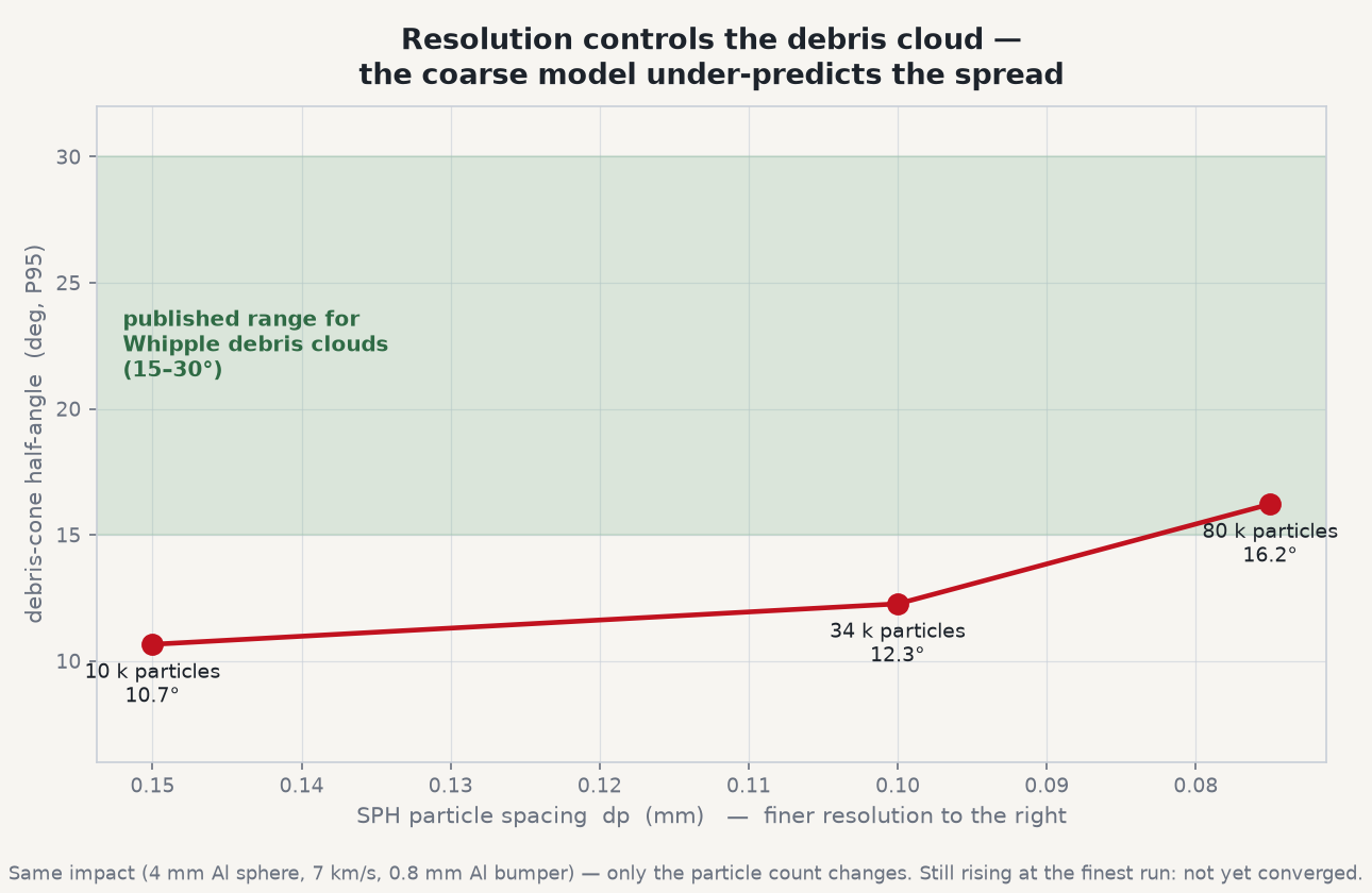
The direction of that error is worth stating plainly, because it decides whether the number is usable. A model that reports a tighter cone than reality is describing a more concentrated cloud arriving at the wall, and it asks the designer for more standoff, not less. The uncertainty falls on the conservative side of the trade. It is also cheap to buy down: eight times the particles cost about three and a half times the wall-clock.
Same weight, one solid plate, no gap — and it loses
Here is the fair objection, and it is the one an engineer should raise first. A Whipple shield is a 0.8 mm bumper plus a 3 mm wall. Perhaps it wins for the dullest possible reason: there is simply more aluminum in the way. So the control is the same total areal mass gathered into 3.8 mm of aluminum in one monolithic plate, no gap, same sphere, same 7 km/s.
It loses outright. Every one of the 9,843 particles ended up behind the plate, still carrying 92 % of the impact velocity. A bare 3 mm wall on its own was likewise perforated. Same mass, no standoff, no protection — nothing in the geometry gives the debris anywhere to spread.
That control also sharpens what the bumper is really doing, and it is not what the word “bumper” implies. At 7 km/s any plate shatters the projectile; the monolithic slab fragments it just as thoroughly. The foil is not uniquely destructive. Its job is to shatter the threat early — and then 100 mm of empty space does the actual protecting. At cloud speed that gap is about fourteen microseconds of flight. Those fourteen microseconds are the entire protection budget, and they are spent letting the cloud open.
The gap is the armor. The foil is just the trigger.
What the design handbooks say this shield should do — and where the model falls short
There is a published yardstick for exactly this configuration, and the honest move is to put our model next to it in numbers. Shield designers size Whipple stacks with ballistic-limit equations — Christiansen’s, in the standard NASA practice — which give the largest projectile a given bumper/gap/wall combination stops. For this stack (0.8 mm aluminum bumper, 100 mm standoff, 3 mm aluminum rear wall, 7 km/s, normal incidence) the equation puts the critical diameter at roughly 6 mm — about 5.5–6.5 mm across plausible rear-wall alloy strengths. Our 4 mm sphere sits well inside that limit: the design literature says this shield stops it with margin.
Our model’s rear wall did not cleanly stop it — element failures begin the moment the cloud front arrives — and that disagreement is substantial, so it gets stated here rather than tuned away. The reasons to trust the equation over the solve in this instance are concrete: energy conservation falls to about 79% precisely in the wall-contact phase (disclosed in the scope note below), and the wall mesh carries only about three elements through its 3 mm thickness — too coarse to distinguish a bulge from a perforation. The rear-wall verdict is this model’s least trustworthy output. The cloud physics upstream — the shatter, the cone, the spreading, and the bumper-versus-monolith comparison — is the part this solve is equipped to speak to.
What the cone angle actually decides
Shield design is a three-way trade between bumper thickness, standoff distance and rear-wall thickness, and the debris-cone angle is the term that couples all three. Because the cloud’s footprint on the wall grows with the square of the standoff, the load per unit area falls away fast with distance — which is why a few extra centimeters of gap routinely beat an extra millimeter of wall on a mass budget, and why standoff is the first thing a shield designer spends on. The geometry does the work; the foil costs almost nothing.
It also sets what the next question costs. Every number here came out of one explicit solve of a geometry defined in minutes, so a different standoff, a heavier bumper gauge or an oblique strike is a parameter change rather than a test campaign — which matters most in exactly the regime where the gun cannot follow.
The real-world connection
The trick generalizes well past orbit, and once you have seen it you start seeing it everywhere: sacrifice something cheap early, then buy distance for the energy to spread. A car’s crumple zone does not survive a crash by being strong — it survives by being long, converting a violent stop into a slower one over half a meter of deliberately weak structure. The crushable liner in a helmet does the same job in 20 mm. Blast standoff at a building is the same idea at the scale of a parking lot: nobody armors the glass to survive a bomb on the doorstep, they move the doorstep. Spaced armor on a vehicle is Whipple’s bumper with a different name.
Every one of those works the way the foil does. It spends the distance, not the material — and distance, unlike plate, is free to a satellite designer right up until the fairing runs out.
The engineering families that need this same toolkit are wider still: hail and bird strike on a leading edge, blade-off containment in a turbine casing, explosive fragmentation, terminal ballistics. Any time the load arrives faster than the material can respond as a solid, strength stops being the answer and geometry starts being it.
Have hardware that has to survive something you cannot slow down — debris, hail, a shed blade, a blast — and you need to know whether standoff or thickness is the better place to spend the mass? The same Ansys workflow behind this shield — explicit dynamics with a meshless projectile, an equal-mass control that proves why it works, and a resolution study that says how far the number can be trusted — is how Rand Simulation helps teams answer impact questions on hardware that has to come home. That’s innovation through insight.