
A Prince Rupert’s Drop vs a Hydraulic Press: Which Gives First?
Drip molten glass into cold water and it freezes into a glassy tadpole: a bulbous head trailing a hair-thin tail. The head is famous for laughing off a hammer — the Hydraulic Press Channel has spent real tonnage trying to crush one. Then you snap the wispy tail with two fingers and the entire drop detonates into powder in a heartbeat. Same piece of glass, two wildly different answers. We wanted the numbers, so we built the drop in Ansys LS-DYNA and ran both acts.
Why one piece of glass has two personalities
A Prince Rupert’s drop is glass frozen under enormous residual stress. The outside cooled and solidified first; when the inside finally cooled and tried to shrink, the already-rigid skin resisted, locking the surface into deep compression and the core into tension. That is the whole trick. Brittle glass fails from tensile surface stress, so a surface locked in compression is extraordinarily hard to crack — any load you apply first has to cancel hundreds of MPa of built-in compression before the surface even feels tension. But that same stored energy makes the core a loaded spring: expose it, and it unzips.
We model this the standard demonstration way — not by baking in an explicit residual-stress field, but with an effective two-layer strength: a tough compression skin that only fails in tension at about 550 MPa (roughly 500 MPa of residual compression plus the ~50 MPa intrinsic strength), wrapped around a primed core that lets go at a low effective stress. Glass is otherwise a simple linear-elastic solid (E = 71 GPa), and a maximum-principal-stress erosion criterion deletes an element when a surface fiber reaches its fracture stress — which is how the crack and the fragmentation propagate.
Act 1: press on the head
Press a rigid platen down onto the 10 mm bulb and the physics is a classic: Hertzian contact. A sphere pushed onto a flat makes a small circular contact patch, and — this is the key — only a thin ring right at the edge of that patch goes into tension. The rest of the contact is pure compression. For glass’s Poisson ratio, that peak surface tension is only about 19% of the peak contact pressure (the classical Hertz result σt = 0.187 p₀). So an enormous squeezing force produces only a modest sliver of surface tension — exactly the wrong way to break a compression-skinned sphere.
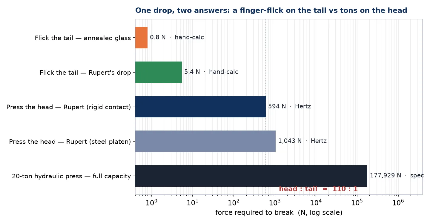
So why does the Hydraulic Press Channel — with a 20-ton (178 kN) press, three hundred times the ~0.6 kN our hand-calc needs — struggle to crack the head? Because a real press does not touch the glass at a mathematical point. Its steel anvil is blunt and it yields. Once the contact conforms, the contact pressure can rise no higher than roughly three times the anvil’s yield strength — about 1.05 GPa for mild steel — which caps the surface tension the glass can ever feel at only ~196 MPa. That is well below the 550 MPa the skin needs. The model predicts the head never cracks on a mild-steel anvil: the anvil dents first. The press gives before the glass does — precisely what the footage shows, where the drop buries itself into the platens.
Is it right? The Hertz control
A point contact on a sphere is a genuinely hard thing to mesh — the stress is mathematically singular at the contact, so a finite-element model always under-resolves the peak on any affordable mesh. That is exactly why we lead with the closed-form Hertz hand-calc as the reference and use the FEA to confirm the mechanism and the trend. Running the press at three mesh densities, the FEA surface tension climbs steadily toward the analytic Hertz curve as the contact is resolved:
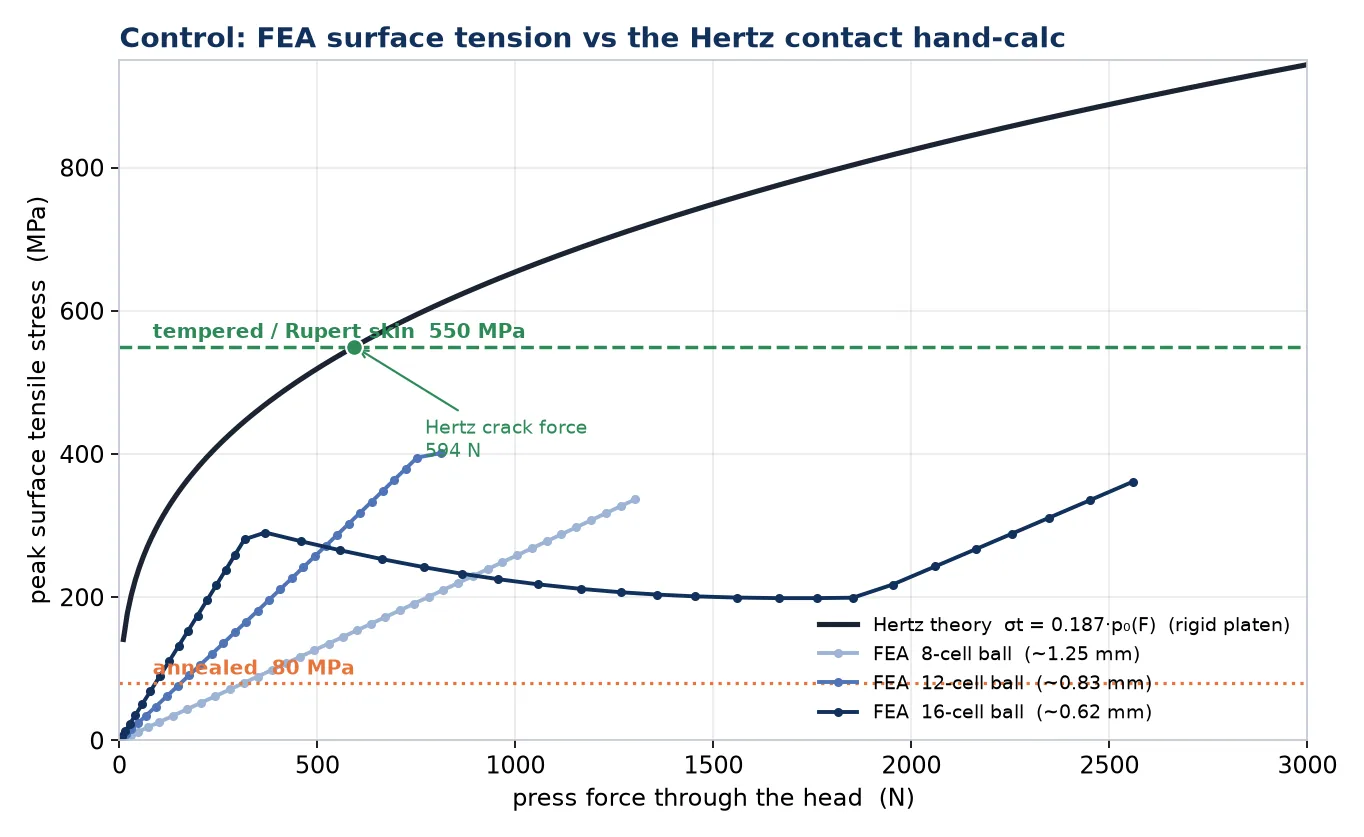
The contrast between the two glasses is the robust part of the answer, and it is regime-dependent in an instructive way: on an idealized point contact the tempered/annealed force ratio scales as the strength ratio cubed (~325×); once the contact conforms — a flat, a yielding anvil, a resolved FE contact — it compresses toward the plain strength ratio (~7×). Where a real system lands between those limits depends entirely on how the contact conforms, which is the engineering point.
Act 2: flick the tail
Now the other end. The tail is a tapered glass fiber thinning to well under a millimeter, and here the loading is pure bending, not contact. Bending a slender rod turns essentially all of the applied load into surface tension on the outside of the bend — the opposite of the Hertzian case, where only a sliver became tension. A cantilever hand-calc says a transverse force of only about 5 N at a 1 mm section reaches the 550 MPa skin strength — and the FEA agrees the tail lets go at just a newton or two where it is thinnest. That is a finger-flick.
And once the skin breaches, the primed core is exposed. In the hero clip above, that is the whole event: the flick cracks the thin tail, the low-strength interior lets go, and the fracture front tears up the tail as the stored strain energy releases. Set beside the head — hundreds of newtons on a hard contact, and uncrackable on a real anvil — the tail giving way at a few newtons is a roughly 100:1 asymmetry, out of one continuous piece of glass.
Round 2: the real pre-stress
Our reviewer asked the right question: could we do better than an effective two-layer strength — could we build the drop with its actual residual stress field inside it, and let the fracture emerge from stress superposition alone? Round 2 is that build. We meshed a single continuous teardrop — a 7 mm bulb blending through the neck into a 60 mm tail that tapers below 1 mm — as 36,288 well-conditioned hex elements, and wrote a spatially-varying initial stress state into every element by hand (LS-DYNA’s *INITIAL_STRESS_SOLID). The field is the classical self-equilibrated tempering solution evaluated on each local cross-section: −480 MPa of equibiaxial compression at the surface, +160 MPa of axial tension in the core, with the compressive skin spanning the outer ~10% of the diameter — anchored directly to the integrated-photoelasticity measurements of Aben et al. (surface compression 400–700 MPa, interior tension 100–200 MPa, skin ~10% of the head diameter). Every cross-section’s axial stress was numerically integrated over the actual element volumes and shifted to a net force of exactly zero — a pre-stress the glass could, in principle, actually carry.

The control: does the field hold?
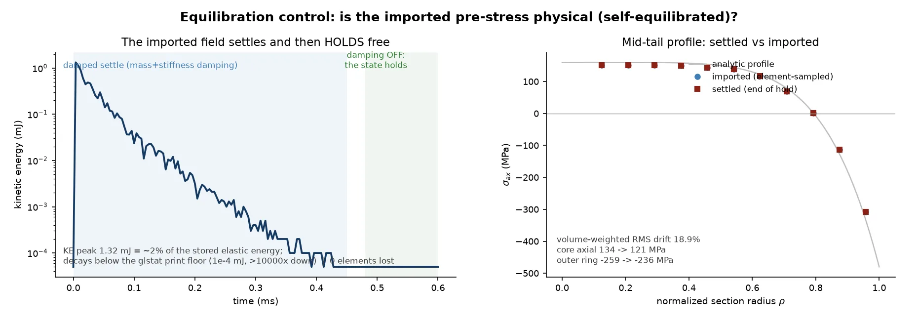
An imported stress state is only physical if the body can actually be in equilibrium with it. So before touching the drop we ran the control: import the field, apply no loads at all, let the model settle under damping, then switch the damping off and watch. The kinetic energy stirred by the settle peaks at ~2% of the stored elastic energy and decays by more than four orders of magnitude; with the damping off, the state simply holds — not a single element lost. The settled field matches the imported one with a volume-weighted RMS drift of 18.9%, and nearly all of that drift lives in the nose and neck transition zones where a section-by-section field is only approximate: through the mid-tail — where Act 2 happens — the settled profile lies on top of the imported one to better than 1%.
The settle taught us something delightful along the way: in an early pilot we left the fracture criteria armed during the equilibration, and the transient waves of the settle set the whole thing off — the drop spontaneously detonated on the virtual bench, exactly the metastability that makes real Prince Rupert’s drops famous. The production sequence equilibrates first and arms fracture afterwards, handing the settled state between runs with the standard LS-DYNA pre-stress workflow (a dynain file).
Fracture from superposition — and the front that runs
With the real field in place, the fracture model becomes almost embarrassingly plain: glass fails at 60 MPa of maximum-principal tension at the (flawed) surface, and at 200 MPa in the (pristine, flaw-free) interior — set safely above the +160 MPa the core already carries, so failure there means a running fracture front, not the resident state. No 550 MPa effective threshold anywhere: whatever protection the skin enjoys now comes from the imported compression itself.
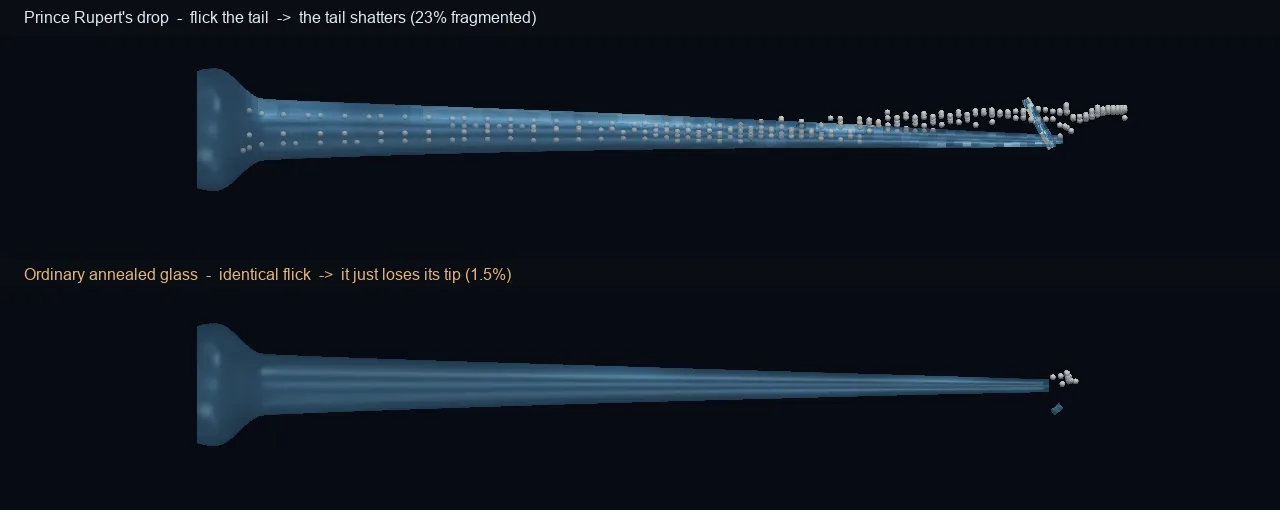
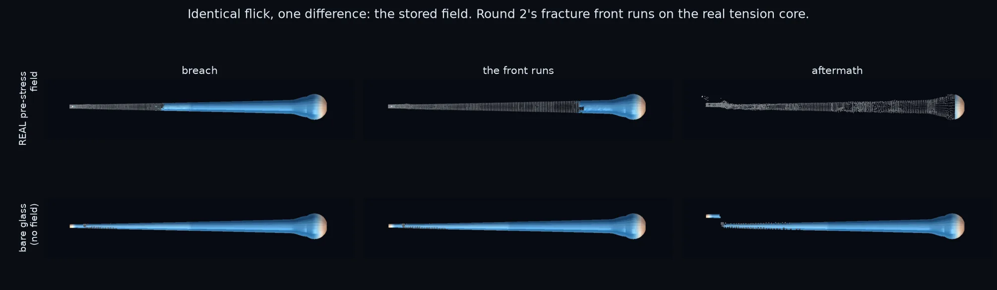
Flick the tail and the superposition delivers. The same finger-flick as round 1 breaches the tail near the tip — and this time the breach does not stay local. The fracture front runs the entire tail, through the neck, and into the head, stopping only at the clamped jaw face: a 61 mm sprint completed in twenty microseconds, consuming 31% of the drop’s elements — including 95% of the compressive skin, which shatters as the core it was balanced against disappears beneath it. The identical flick on a bare, field-free copy of the same drop chips 2.4% off the tip region, and nothing runs anywhere. The stored field is the explosion.
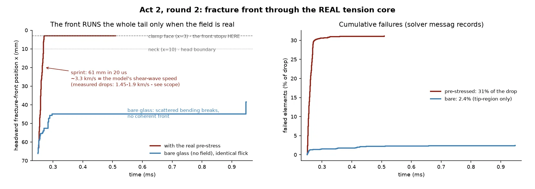
How fast should it run? High-speed photography of real drops clocks the disintegration front at 1.45–1.9 km/s. Our front sprints at ~3.3 km/s — which is, not coincidentally, the shear-wave speed of the model glass. An element-deletion front is free to ride the elastic wave that triggers it, while a real crack front is throttled by crack-branching physics this model deliberately does not contain. Same order of magnitude, right qualitative behavior, and a clean explanation for the factor of two — that is exactly the standing of an erosion-front model, now measured rather than waved at.
Act 1 rematch: pressing on a truly pre-stressed head
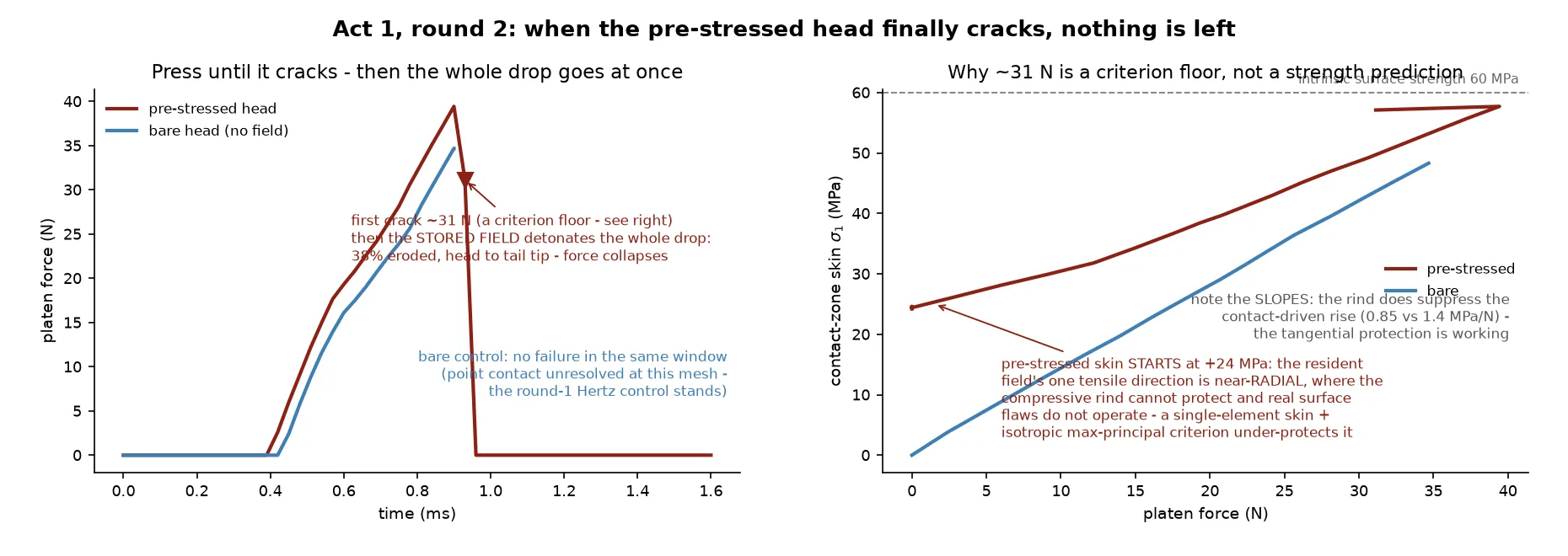
Pressing the pre-stressed head delivered the other half of the Hydraulic Press Channel story: when a Prince Rupert’s drop finally does crack under a press, there is nothing left to sweep up. The moment the first skin elements let go near the contact, the stored field takes over and the entire drop detonates — head, neck and all 60 mm of tail, 38% of all elements consumed in half a millisecond, more than the flick itself destroyed (the flick’s clamp shielded the head; the press shields nothing). The bare control head, squeezed identically, lost nothing at all in the same window.
And the crack-force number itself? Here round 2 earns its keep by being honest about what it found. The model’s first crack arrives at only ~31 N — and the diagnosis is more interesting than the number. At this mesh the compressive rind is one element thick, and inside that element the resident field’s only tensile direction is the through-thickness (radial) one — a direction the tempering compression cannot protect, and one in which real glass fracture (driven by surface flaws loaded in surface-tangential tension) does not operate. An isotropic maximum-principal criterion cannot tell those directions apart, so it fires early: the ~31 N is a criterion-resolution floor, not a strength prediction — the telling detail is that the rind visibly suppresses the contact-driven stress growth (the tangential protection working exactly as imported). The quantitative crack-force reference for Act 1 therefore remains round 1’s Hertz-plus-superposition hand-calc — hundreds of newtons on a hard contact, and never on a real yielding anvil — while round 2 contributes what the hand-calc never could: the demonstration that the first crack, whenever it comes, is total. Next steps on our list: a multi-element rind and a direction-aware (surface-tangential) fracture criterion, which together close exactly this gap.
What round 2 changes — and what it doesn’t
Round 1’s numbers stand: the Hertz hand-calc, the mesh-convergence story, the pressure-cap argument for why a real press dents before the head cracks, and the ~100:1 head-to-tail asymmetry are unchanged — round 2 does not touch them. What round 2 adds is the mechanism, demonstrated rather than idealized: a measured, self-equilibrated residual field that survives its own equilibration control; a fracture criterion with nothing baked in; and a disintegration that emerges — the front running the tension core and the skin shattering as its support vanishes, the two-order-of-magnitude asymmetry now produced by superposition instead of assumed through an effective strength.
Need to know whether a brittle part survives an impact, a press, or a drop — with a real fracture threshold instead of a guess? The same Ansys explicit-dynamics workflow — a resolved contact model, a physically-grounded failure stress, a closed-form control, and an honest sensitivity bracket — is the kind of workflow that helps teams qualify glass, brittle housings, and impact events. Innovation through insight.