How Much Power Does a Box Fan Make as a Wind Turbine?
Stand a box fan in a stiff breeze instead of plugging it in, and the blades start to turn on their own. It looks like free electricity: the wind does the spinning the motor used to do. So how much power could you actually pull out of a $20 box fan run backwards as a wind turbine -- enough to charge a phone? a laptop? We put a generic 20-inch box fan in a steady 20 mph (8.94 m/s) wind in Ansys Fluent, spun the rotor across its whole speed range, and measured the shaft power it can extract at each speed.
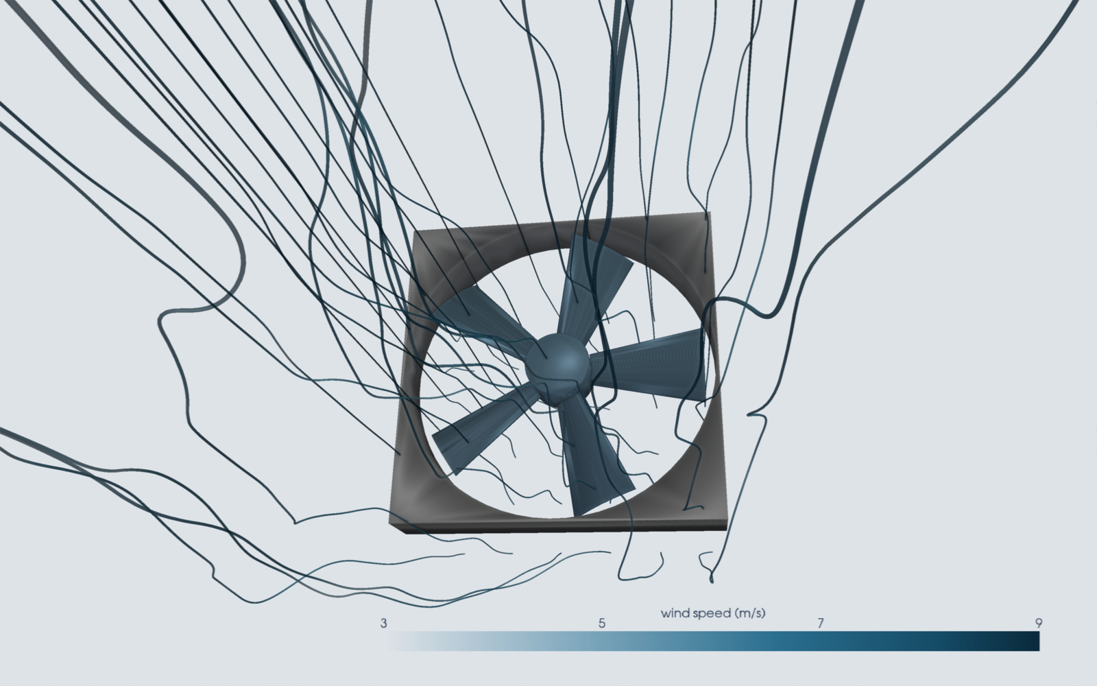
The setup: a fan is a turbine run backwards
A fan and a wind turbine are the same machine pointed in opposite directions. A fan puts electrical power in at the motor and pushes air; a turbine lets moving air push the blades and takes mechanical power out at the shaft. So a box fan really can act as a turbine -- the question is how good a one. We modeled a self-authored, brand-free 20-inch box-fan-style rotor -- a square housing, a central hub, and five wide, cambered sheet-metal blades set at a fixed pitch -- inside a large open wind domain, and solved the steady airflow with a rotating-frame (MRF) RANS model in Ansys Fluent. By imposing a rotor speed and reading the aerodynamic torque on the blades, shaft power is simply P = torque × angular speed. Sweep the speed and you trace the fan's entire operating curve.
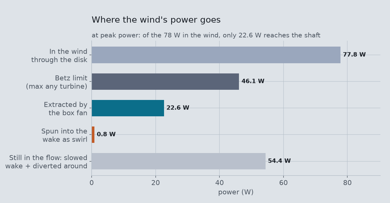
There is a hard ceiling to keep the answer honest. A 20 mph wind carries about 77.8 W of kinetic power through the 0.48 m circle the blades sweep (that is ½ρAv³). No turbine of any kind can take more than the Betz limit, 59% of that -- about 46.1 W here. A modern wind turbine recovers roughly 45% of the wind (Cp ≈ 0.45). Everything the box fan does has to fit under those numbers.
Where the wind's energy goes
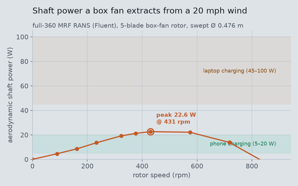
It helps to follow the 77.8 W the wind carries through the swept circle. The Betz limit says no turbine can take more than 46.1 W of it; our box fan captures only 22.6 W as shaft power, about 29% of the power in the wind. The flow slows as it crosses the disk — from 8.94 m/s to about 6.9 m/s, a 23% drop — and simple one-dimensional actuator-disk (momentum) theory says a slowdown that large could in principle feed a power coefficient near 0.55. Only 0.29 actually reaches the shaft: the cambered plates capture the wind's momentum but then dump most of it into separation and swirl instead of turning it into torque. Where does the other ~55.2 W go? A wake-plane integral about 1.3 rotor-diameters downstream finds only about 0.8 W spun into the wake's swirl — rotational energy the blades stirred up but the shaft never collected. The remaining ~54.4 W is still in the moving air: some rides on in the slowed wake behind the frame, but a large share simply diverts around the high-solidity disk rather than giving up its momentum to the blades. That is the signature of a rotor built to move air, not to catch it.
Why a box fan is a bad turbine
The shape that makes a good fan makes a bad turbine. A box fan's blades are wide, flat, shallow plates set at one steep pitch from root to tip. That high “solidity” (lots of blade area blocking the disk) and coarse pitch are exactly what you want to shove a lot of air at low speed. Run backwards, those same blades stall: the wind hits them at a steep angle, the flow separates off the back, and much of the air simply piles up and diverts around the disk rather than giving up its momentum to the blades. Little of the wind's energy reaches the shaft.
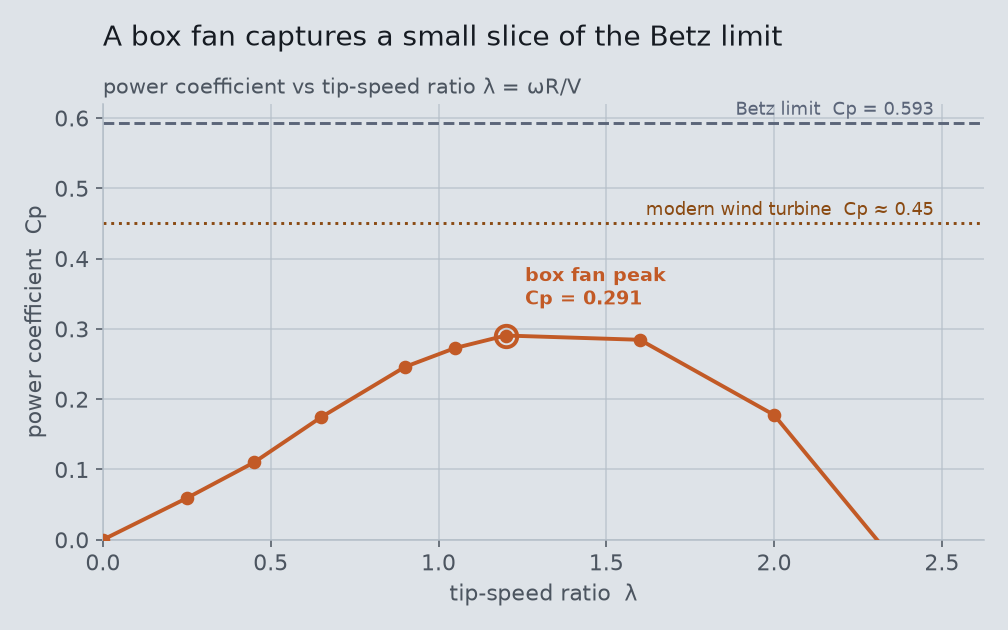
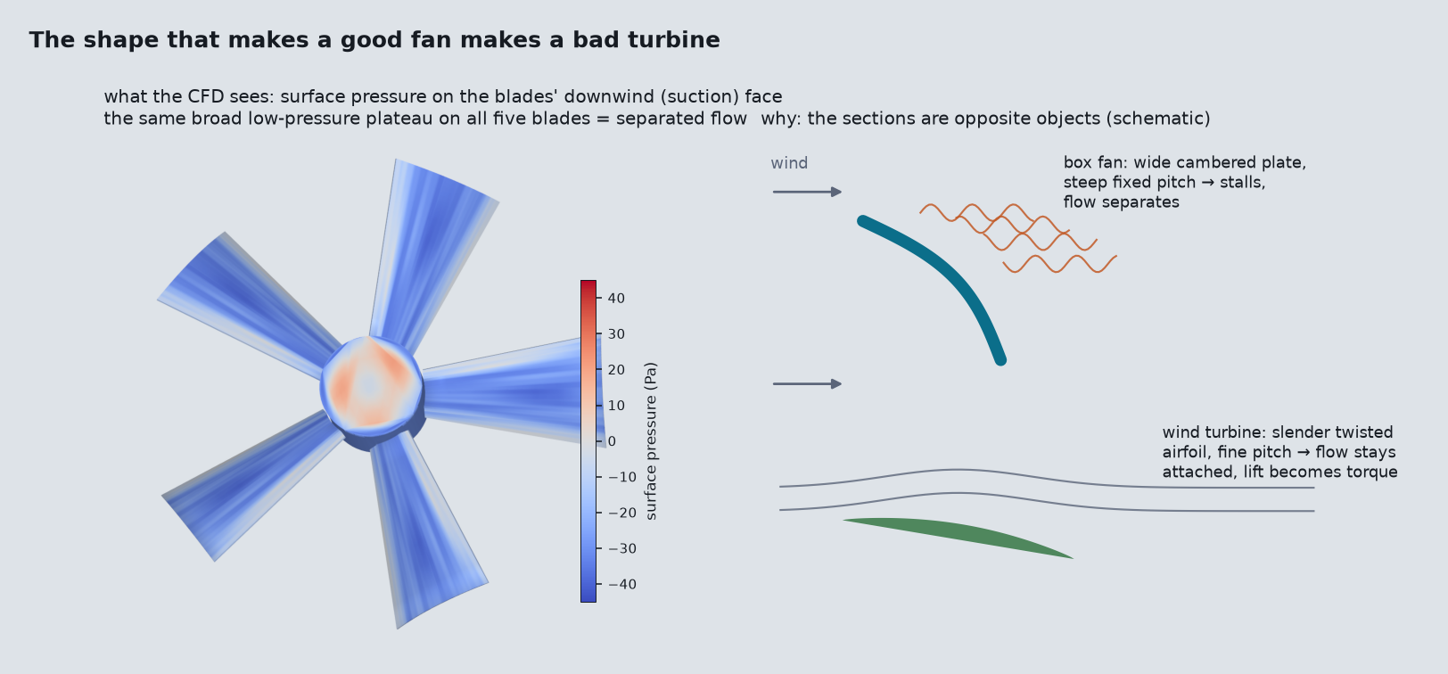
A real turbine blade is the opposite object: a slender, twisted airfoil, only a few blades, set fine so it slices the wind at a shallow angle and spins fast (high tip-speed ratio). The twist keeps every radius at its best angle of attack; the slimness keeps the flow attached so it turns lift into torque instead of dumping energy into a separated wake. The box fan has none of that -- no twist, too much blade, too steep a pitch, spinning too slowly. It is a superb air-mover and, run backwards, a mediocre air-harvester. That contrast, not the raw wattage, is the real lesson: turbine blades look nothing like fan blades because they are solving the opposite problem.
The receipts
Every point on the operating curve is a separate steady MRF solve; the torque monitor had to go flat (<1% drift across the final 300 iterations) for a point to count as converged, and the headline peak is read only from converged points:
| rpm | λ | |T| (N·m) | P (W) | converged |
|---|---|---|---|---|
| 0 | 0.00 | 0.494 | 0.0 | yes |
| 90 | 0.25 | 0.490 | 4.6 | yes |
| 161 | 0.45 | 0.506 | 8.6 | yes |
| 233 | 0.65 | 0.555 | 13.6 | yes |
| 323 | 0.90 | 0.566 | 19.1 | yes |
| 377 | 1.05 | 0.538 | 21.2 | yes |
| 431 | 1.20 | 0.501 | 22.6 | yes |
| 574 | 1.60 | 0.368 | 22.1 | yes |
| 718 | 2.00 | 0.184 | 13.8 | yes |
| 897 | 2.50 | 0.093 | -8.7 | yes |
Mesh independence at the peak point. The peak operating point re-solved on both a coarser and a finer mesh; the blade torque the whole story rests on stays within 4.0% of the base-mesh value:
| mesh | cells | |T| (N·m) | P (W) | ΔT vs base | converged |
|---|---|---|---|---|---|
| base (sweep) | 1,193,141 | 0.501 | 22.6 | — | yes |
| coarse | 720,375 | 0.513 | 23.1 | +2.4% | yes |
| fine | 2,421,811 | 0.522 | 23.5 | +4.0% | yes |
Have a real turbomachinery or wind-energy question -- a rotor to design, a fan or pump curve to predict, a turbine sited in a tricky flow? The same Ansys CFD workflow that spun this box fan across its whole operating range is how Rand Simulation maps torque, power, and efficiency for rotating machinery before anything is built. That is innovation through insight.