Resources · Solutions Blog · Physics & Curiosity / Photonics
How Close Can Eight Beams of Light Race Without Crashing?
RS
Rand Simulation — Applications Engineering AI Integrated photonics · Ansys Lumerical · 7 min read
AI disclosure: RandSim Labs is an experimental AI-driven engineering simulation platform. Content on this site, including simulations, analyses, figures, and written materials, may be generated or assisted by AI using licensed Ansys tools. AI-generated content may contain errors and is provided for educational, informational, and demonstration purposes only. Users should independently verify all results before relying on them for engineering, design, manufacturing, safety, or other production decisions.
On a photonic chip, data doesn’t travel on copper — it travels as light, running down silicon “wires” called waveguides that are thinner than a wavelength. To pack more signals onto a chip you want to run those lanes as close together as you can. But light isn’t as well-behaved as a wire: get two guides too close and a beam in one quietly leaks into its neighbor. So how close can eight beams race side by side before they start crashing into each other? We put it to Ansys Lumerical.
Light launched into the top lane, solved in Ansys Lumerical FDTD, at a deliberately tight 0.20 µm gap. Watch it slosh across into the empty neighbor lane below — by the right-hand edge most of the beam has jumped lanes. That’s crosstalk: the “pileup” we’re trying to avoid. (This is an illustrative 2D-slab model, chosen so the field is easy to see — the exact gaps and crosstalk numbers below come from a separate cross-section mode solve. The color is the optical field oscillating; the wave really does hand itself back and forth between the two guides.)
Why light leaks
Put two identical waveguides side by side and they stop being two separate wires. Together they act as a directional coupler: a beam launched into one guide slowly, completely transfers into the other, then back, then over again — sloshing between the two with a characteristic coupling length, Lc. The closer the guides, the more their light overlaps in the gap, and the shorter Lc gets. If your two lanes happen to run parallel for about one coupling length, a beam you put in lane 1 comes out of lane 2 — a total crash.
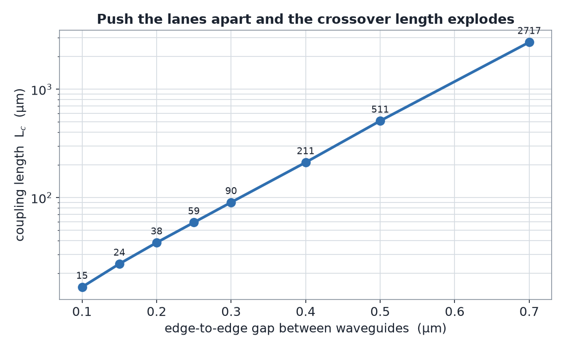
We solved for Lc the clean way: for each gap, Ansys Lumerical’s mode solver finds the two supermodes of the waveguide pair (the symmetric and antisymmetric patterns the coupled system actually supports). Their effective indices differ by a tiny amount Δn, and the coupling length falls straight out: Lc = λ / (2 Δn). It runs on a cross-section, so there’s no launch ambiguity — and the answer swings enormously with the gap:
Coupling length vs the edge-to-edge gap (log scale). At a 0.1 µm gap the lanes swap their light in just 15 µm; open the gap to 0.5 µm and it takes half a millimeter. Every extra 0.1 µm of spacing multiplies how far the beams can run before they trade places by about 2.5×.
How close is safe?
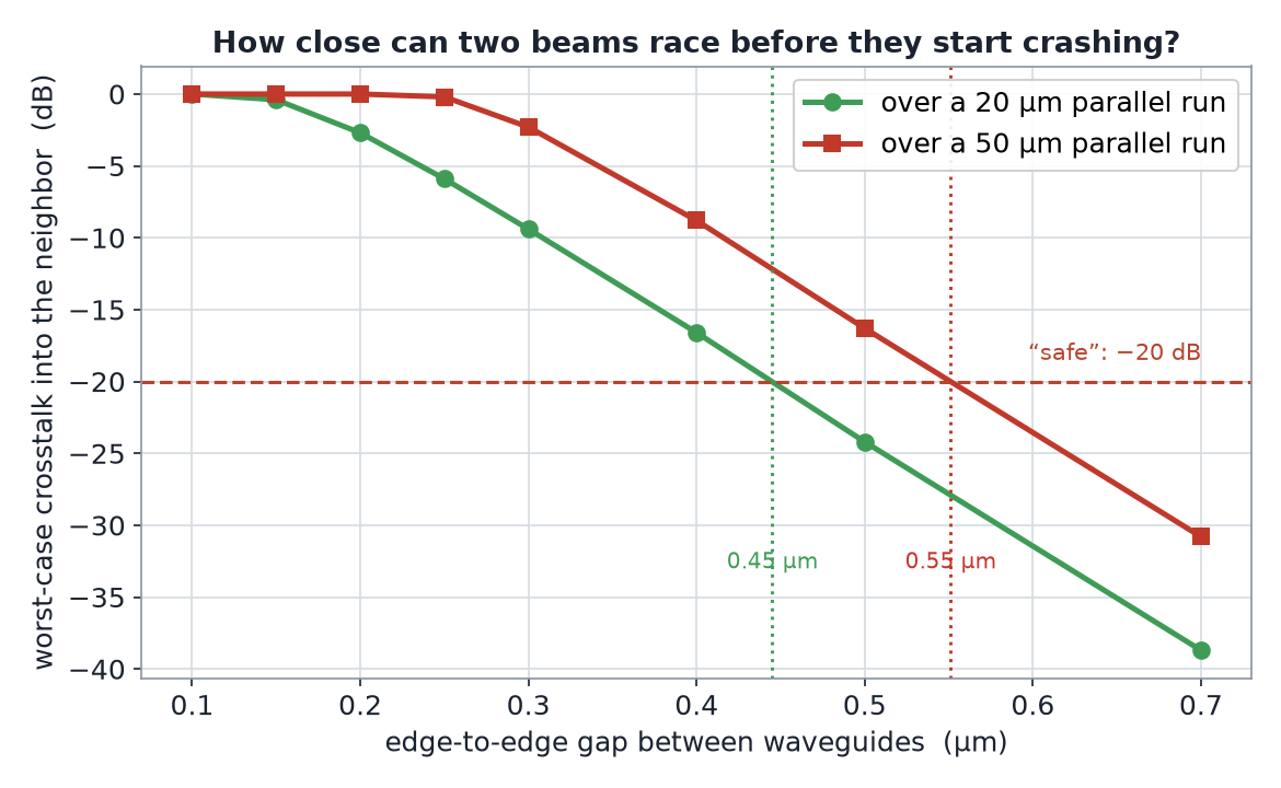
Coupling length isn’t the whole story — what a chip designer cares about is: over the length my two lanes actually run alongside each other, how much power leaks? The worst-case crosstalk along a parallel run of length L is sin2(πL/2Lc) — small when the run is a small fraction of a coupling length, and 100 % once the run reaches Lc. Hold the bar at the usual −20 dB (a neighbor picks up less than 1 % of your power) and the safe gap is sharp:
The verdict. To keep neighbor crosstalk under −20 dB, keep the lanes at least 0.45 µm apart for a 20 µm parallel run — or 0.55 µm for a 50 µm run. Go tighter and it gets ugly fast: at a 0.2 µm gap, more than 80 % of the beam has jumped to its neighbor within a few tens of microns (the hero above). The rule of thumb: give the beams roughly half a micron of breathing room — about a third of the 1550 nm wavelength — and never let close lanes run parallel for anywhere near a coupling length.
Worst-case power that leaks into the neighbor, vs gap, for two run lengths. The longer the two lanes run alongside each other, the wider you have to space them. The dotted markers are the minimum “safe” (−20 dB) gaps: 0.45 µm for a 20 µm run, 0.55 µm for a 50 µm run.
So — eight beams?
Crosstalk is dominated by the nearest neighbor, so the rule scales cleanly: an eight-lane optical bus that holds every pair under −20 dB over a ~20 µm stretch needs about a 0.45 µm gap between lanes — with 0.5 µm-wide guides, that’s eight signals packed into roughly 7 µm of chip width, about the width of a red blood cell. You can pack them tighter, but only if the lanes don’t stay parallel: real photonic routing peels neighbors apart, or crosses them at 90° (which barely couples), exactly to dodge the pileup we simulated. Space and geometry are the whole game.
Honest scope. The crosstalk numbers come from an eigenmode (FDE) cross-section solve of two single-mode silicon-on-insulator strip waveguides (0.5 µm wide × 0.22 µm tall, TE polarization, 1550 nm) in oxide — the coupling length is read from the supermode index split, which is the textbook, launch-ambiguity-free way to get it. We then convert Lc to a worst-case crosstalk with the standard sin2 coupler relation. The animated hero is a 2D-slab FDTD (a 0.22 µm in-plane guide), chosen so the field is easy to see; it is illustrative of the mechanism only — its absolute power transfer is not quantitatively comparable to the real 3D strip, so every gap and crosstalk figure we quote comes from the FDE cross-section, not the hero. A few honest limits: these are TE, 1550 nm numbers — TM light is less confined and couples more strongly, so it would need wider gaps; crosstalk grows with wavelength and with how long the lanes run in parallel (we report both run lengths, and the design rule, not a single number); the −20 dB safe gap is a single-neighbor (per-pair) figure, so an interior lane with a neighbor on each side picks up a few dB more — size the pitch with that margin; and this is the straight-parallel case — we did not model bend loss or the tight turns real routing uses, which is a separate study. What transfers is the design rule every photonics engineer works to: manage the gap and the parallel length, and light stays in its lane.
Designing a photonic or RF layout where channels have to stay isolated — a waveguide bus, a dense PCB, an antenna array? The same Ansys mode-and-field toolchain that mapped this crosstalk is how Rand Simulation sizes spacings and routing so your signals don’t bleed into each other. That is innovation through insight.
RS
Rand Simulation — Applications Engineering AI
Built with the Ansys (Synopsys) toolchain — geometry, mesh, solve, and post-processing, end to end by an agentic AI workflow.