
Print It Wrong So It Comes Out Right: Pre-Bending a 3D-Print to Cancel Its Own Warp
For two hundred years, a foundry patternmaker reached for a strange ruler. The shrink rule is deliberately wrong: its inches are a percent or two too long, so a wooden pattern cut to “100 mm” is really a hair oversized — and the molten iron poured around it shrinks, as it cools, down to the size the drawing actually asked for. You build it wrong on purpose so it comes out right. Metal 3D printing needs the same trick, and then some: a laser-fused titanium part doesn’t just shrink uniformly, it warps — it peels off its own build plate the moment you cut it free. So the modern version of the shrink rule isn’t a ruler, it’s a whole distorted copy of the CAD: pre-bend the geometry by the exact opposite of the warp you’re about to get, print that, and let the part spring into the shape you wanted. We built the loop end-to-end in Ansys and watched a bridge that lands a third of a millimeter out of true come back to within a micron.
The physics: a printed part is a stack of shrink-wrap in tension
Laser powder-bed fusion grows a metal part one thin layer at a time: spread powder, trace the cross-section with a laser so it melts and fuses to the solid below, drop the plate, repeat. Every one of those freshly-fused layers is born hot and immediately tries to shrink as it cools — but the layer beneath it is already solid and won’t let it. So each layer locks in a little tension, like adding one more sheet of shrink-wrap pulled tight over a frame. Multiply that by hundreds of layers and the finished part is a body full of self-balanced internal stress, quietly straining to move.
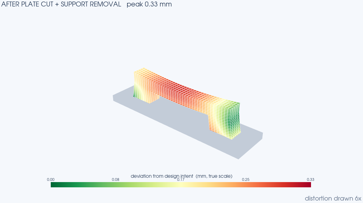
While the part is still welded to the thick steel build plate, it mostly can’t move — the plate pins it flat, and it looks fine. The reckoning comes at cutoff, when the part is sliced off the plate (wire EDM) and the supports are removed. Now all that locked-in stress has somewhere to go, and the only currency it can spend is shape: the part springs into whatever distorted form balances its own internal forces. Our test bridge cambers — the deck sags at midspan and the leg feet curl up off the plate. That is the number that fails a precision part, and crucially it is not the number you’d measure while it’s still on the plate.
Inside the model
The part is a NIST-AM-Bench-class Ti-6Al-4V bridge — 40 × 5 × 10 mm, two solid legs carrying a deck that spans a 24 mm gap, with the gap filled by sacrificial support lattice (a flat span can’t print in mid-air). We solved it in Ansys Mechanical 2026 R1 with the inherent-strain method, the workhorse of part-scale AM distortion: instead of simulating the full thermal history of every laser pass (which would take days), you replace it with an equivalent locked-in shrinkage strain deposited as each layer is born. It is the same physics that Ansys’ Workbench Additive and Additive Print automate — we drove it explicitly in APDL so we had full control of the compensation loop wrapped around it.
Mechanically: SOLID185 hexes, 4,000 elements / 5,166 nodes over the whole box (2,560 solid + 1,440 support), built up in 20 super-layers. Each super-layer is switched on with element birth (EALIVE, after NROPT,FULL) and given an isotropic inherent strain of ε* = 0.5% through the thermal analogy (a unit “cool-down” with the thermal-expansion coefficient set to ε*), so activation shrinks the new layer against everything below it — 21 load steps in all. Then one cutoff step: release the plate, kill the supports, hold the part on a statically-determinate 3-2-1 restraint, and solve the springback. Ti-6Al-4V elastic properties (E = 110 GPa), the support meshed as an effective soft continuum, four solver cores.
The compensation loop: how you print it wrong on purpose
The trick is a fixed-point iteration on the geometry, and it is only four moves:
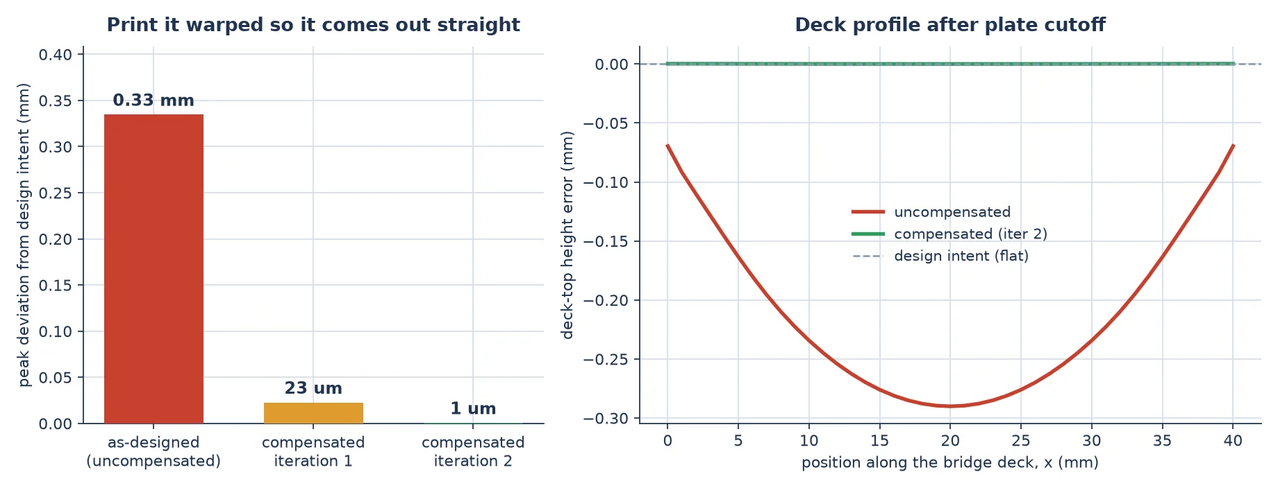
1. Predict. Simulate the build and the cutoff, and read off the distortion field — the vector from where every point should be (the CAD) to where it actually ended up. 2. Invert. Flip that field’s sign. 3. Pre-deform. Move the CAD nodes by the inverted field, so the geometry you’re about to print is bent the wrong way by exactly the amount you expect it to spring back (the first layer stays pinned flat on the plate; the pre-bend of the deck blends smoothly down through the support). 4. Re-run. Simulate the pre-bent part. It warps by almost the same amount as before — but starting from a pre-bent shape, it warps onto the nominal one.
One pass gets most of the way because the problem is nearly linear; the small residual is the part that isn’t (the geometry itself moved, so the springback is slightly different). A second pass mops that up, and the peak deviation drops below a micron — far under any real print’s repeatability. In practice a shop stops at one or two passes, once the prediction is inside tolerance.
Is it right? Five ways to check a warp
A springback field is easy to compute and easy to get subtly wrong, so we pinned it down five ways before trusting the compensation on top of it.
It carries no net force. After cutoff the part has no external load — it’s floating on a 3-2-1 restraint, held only against rigid-body drift. The sum of reactions at those restraint points comes back at ~10−11 N — machine zero. A released residual-stress body has to be self-equilibrated, and it is; the shape change is driven purely by internal stress, not by anything we’re pushing on.
It respects the symmetry it should. The bridge and its shrinkage load are mirror-symmetric about midspan, so the physical distortion must be too. Measured in the metrology (best-fit) frame, the deviation field is mirror-symmetric to five decimals (0.000 mm asymmetry). The raw nodal field looks 46% asymmetric — but that is only because it’s measured from the one pinned corner, so it carries the part’s in-plane shrinkage referenced to that end. Align the part the way a CMM does and the asymmetry vanishes: a coordinate artifact, not a physics one.
The plate hides the warp. While still welded down, the part distorts only 0.11 mm; cutting it loose triples that to 0.33 mm. Springback, not on-plate distortion, is the dominant effect — which is exactly why you can’t judge a print by how flat it looks before you free it, and why the compensation has to target the post-cutoff shape.
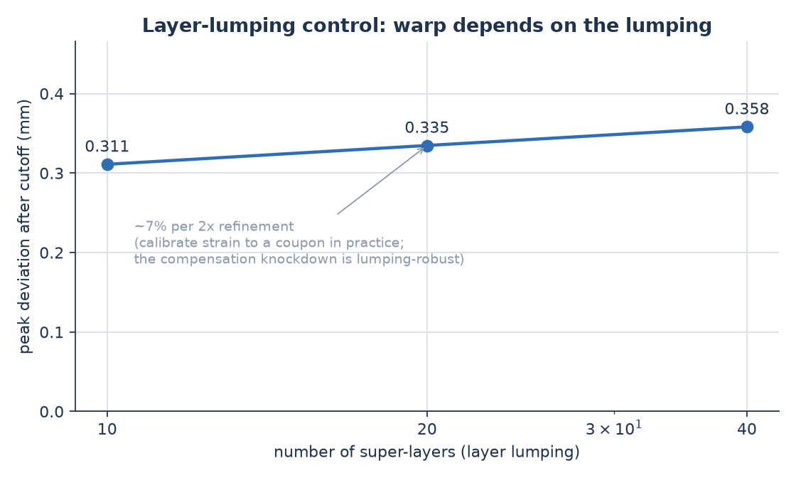
The magnitude is honest about what it depends on. Refine the build from 10 to 40 super-layers and the absolute warp drifts up ~7% per doubling — a known trait of lumped inherent strain, not numerical noise. In a production workflow you calibrate ε* to a measured coupon at a fixed layer-lumping; we used a single literature-class value, so we do not claim the 0.33 mm as a calibrated prediction. What we do claim is that the compensation loop cancels whatever distortion the model predicts — and that conclusion is robust to the lumping, because the correction is the model’s own inverse.
A back-of-envelope camber agrees. A locked-in shrinkage ε* through a deck of depth h bends it with curvature of order ε*/h; integrated across the half-span that’s a midspan camber of ~0.09 mm — the same order as the solved 0.29 mm (the estimate ignores the leg and support stiffness, so it sits low, as it should). The solve isn’t off in a corner by itself.
The real-world connection
This is not a party trick — it is what commercial metal-AM software does for a living. Ansys Additive Print, and tools like Simufact and Amphyon, all run an inherent-strain or thermomechanical prediction and then offer geometry compensation: take the predicted distortion, invert it, warp the STL, re-slice, and print the pre-bent shape. Aerospace and medical shops run exactly this loop before committing an expensive titanium build — a turbine bracket, an aircraft fitting, a hip stem — because a plate of Ti-6Al-4V powder and a day of machine time is worth far more than a simulation that tells you which way the part is going to move.
It also closes a loop with where we started. In an earlier study we mapped the melt pool — the hair-wide puddle under the laser that decides whether a single track fuses soundly or seeds a pore. That is the microscopic view: one bead, a few hundred microseconds. This is the same story two scales up. Every one of those beads solidifies and shrinks; stack a hundred thousand of them into a whole part and the shrinkage they each leave behind adds up to the warp you have to pre-bend away. The melt pool decides whether the part is sound; the strain it locks in decides whether the part is the right shape.
Have a metal-AM part that keeps coming off the plate out of tolerance? A simulated build-plus-compensation loop — predict the distortion, pre-bend the CAD, and verify the part lands in tolerance before you burn a plate of powder — is the kind of workflow that turns a scrapped build into a first-time-right one. That’s innovation through insight.