
Too Cold It Won’t Fuse, Too Hot It Drills a Hole: Mapping a Titanium 3D-Printing Window
In 2015 GE Aviation did something that used to be impossible: it printed a jet-engine fuel nozzle — a part that had been twenty brazed pieces — as a single block of metal, grown out of powder one hair-thin layer at a time. The part flew. The catch nobody puts in the brochure is that two nozzles printed on the same machine, from the same powder, can come out completely different: one flight-ready, its twin quietly riddled with pores — because the laser was forty watts too hot, or a hair too slow. The whole difference lives in a pool of molten titanium about the width of a human hair that exists for a few hundred microseconds. So we mapped it.
The physics: the part is only ever as good as one moving puddle
Laser powder-bed fusion (LPBF) builds a metal part the way you’d frost a cake in reverse: spread a 30-micron layer of titanium powder, trace the cross-section with a focused laser so the powder melts and fuses to the solid below, drop the plate, spread the next layer, repeat tens of thousands of times. Everything that matters — density, strength, whether the part is airworthy — is decided in the melt pool: the tiny, moving puddle of liquid metal under the beam. Get the pool right and each track welds cleanly to its neighbors and to the layer beneath. Get it wrong in one of two directions and you seed the defects that fail the part later.
Too little energy (low power, high speed) and the pool is shallow and narrow: it doesn’t reach down far enough to remelt the previous layer, and it doesn’t spread wide enough to overlap the neighboring track. The un-melted gaps become lack-of-fusion pores — jagged voids that act like pre-installed cracks. Too much energy (high power, low speed) and the opposite happens: the pool gets so hot it boils, and the recoil of the vapor punches a deep, narrow cavity into the metal — a keyhole. Keyholes are unstable; they collapse and pinch off bubbles of gas that freeze in place as near-spherical keyhole pores. Between the two failure modes is a window of settings that does neither. Finding that window is most of process development for a new alloy or machine.
Inside the model
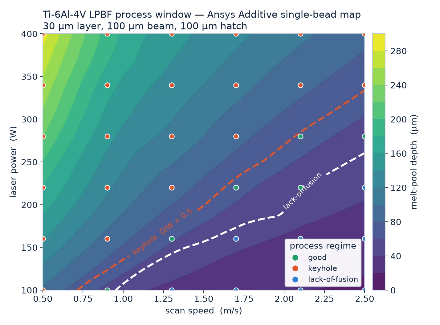
We drove Ansys Additive — the same LPBF-physics engine Ansys ships for print simulation — through its Python API (PyAdditive), headless, on Ansys 2026 R1. The workhorse here is the single-bead simulation: it computes the thermal field of one laser track dragged across a powder layer and reports the melt pool’s width, depth and length. The material is stock Ti-6Al-4V (the aerospace titanium), with Ansys’ calibrated laser-absorption model. We fixed the layer at 30 µm and the beam at a 100 µm spot, then swept a 6 × 6 grid of laser power (100–400 W) against scan speed (0.5–2.5 m/s) — 36 melt-pool solves in all, run four at a time. For each point we read the pool geometry back and sorted it into a regime by two textbook criteria: a keyhole once the pool is deeper than it is wide-enough-to-be-a-half-circle (depth/width > 0.5), and lack of fusion once the pool is too shallow to remelt the layer below or too narrow to overlap its neighbor (the Tang–Beuth overlap criterion at a 100 µm hatch).
Is it right? Three ways to check a puddle you can’t see
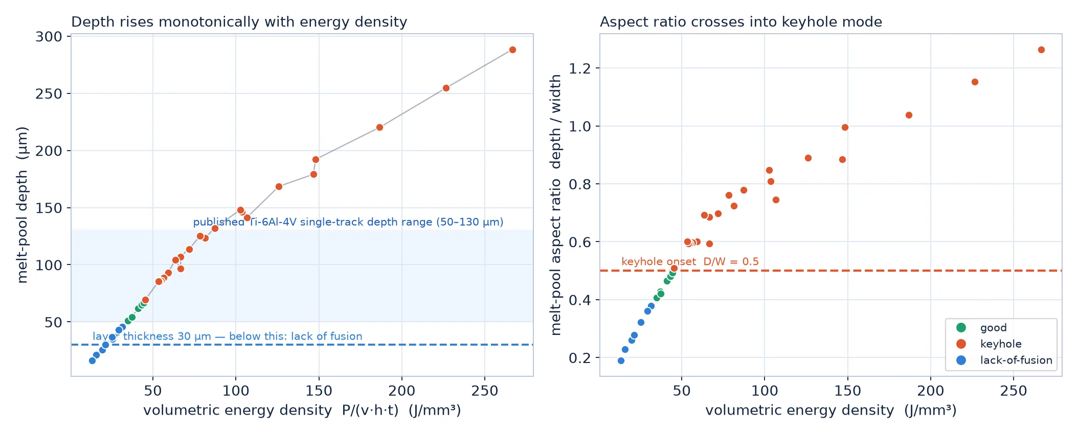
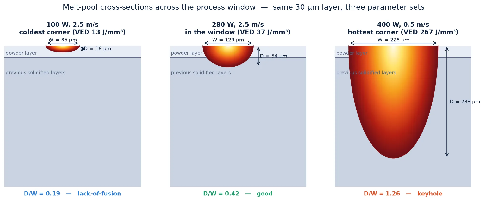
A melt pool a hundred microns across, gone in a fraction of a millisecond, is not something you eyeball — so we pinned the numbers three independent ways. First, the dimensions: in the conduction and good-window regimes the solver’s pools are 85–180 µm wide and ~30–115 µm deep, squarely inside the range laboratory single-track studies report for Ti-6Al-4V LPBF (widths of order 100–180 µm, depths of tens to ~130 µm as power and speed vary). Only in the deliberately over-powered keyhole corner do they run deeper — to 288 µm at 400 W and 0.5 m/s, deeper than the pool is wide — which is exactly what a keyhole is. Second, the trend: melt-pool depth rises monotonically with volumetric energy density, exactly as the physics demands — no noise, no reversals — and crosses the layer thickness (the fuse/don’t-fuse line) right where the geometry says it should. Third, the keyhole criterion itself is not ours: a melt pool deeper than about half its width is the widely-used aspect-ratio marker for the conduction-to-keyhole transition (King and co-workers established it on 316L; it generalizes). All three agree on where the walls of the window are.
Why the shape of the pool, not just its size
The single most useful thing the solver gives you is not a pass/fail flag — it’s the shape of the pool, and the two failure modes are shapes, not numbers. A lack-of-fusion pool is a shallow saucer that leaves cold metal untouched between passes. A keyhole pool is a deep, skinny puncture. Same alloy, same machine; the only thing that changed is how much energy you poured into a moving spot and how fast you dragged it.
The real-world connection
This is not an academic nicety. When Argonne and NIST researchers put an LPBF machine in front of a synchrotron X-ray beam and filmed the melt pool in real time, they watched keyholes open, wobble and pinch off pores exactly the way the aspect-ratio criterion predicts — the defect being born, frame by frame. It is why every serious metal-AM operation — GE’s printed engine parts, SpaceX’s SuperDraco thruster, Relativity’s rockets — spends its first weeks on a new alloy or machine doing exactly what we just did in software: single-bead and small-coupon sweeps to find the window before committing a real build. Doing that first pass in simulation means arriving at the machine with a map instead of a blank grid — fewer wasted plates of expensive titanium powder, and a defensible reason for every number on the build sheet.
Bringing a new alloy, machine or part into metal AM and staring at a blank parameter grid? A simulated single-bead and coupon sweep — melt-pool geometry, the keyhole and lack-of-fusion walls, the energy-density window — is the kind of workflow that turns weeks of trial-and-error builds into a map you arrive with. That’s innovation through insight.