
Could a Skyscraper Become an Emergency Antenna After an Earthquake?
Here is a piece of radio history most people have never noticed: the towers that broadcast AM radio are not carrying antennas — they are the antennas. Many are bolted straight to grounded foundations and driven by nothing more than a slanted wire running from a ground-level feed box up to a point partway up the steel. If a grounded lattice of structural steel can be a transmitter, an anonymous community member asked the disaster-movie question: after a major earthquake flattens the cell network, could you clip a wire to a surviving office building and put a city back on the air? We put a 96-meter steel skeleton into Ansys HFSS to find out — intact, and then broken.
The physics: a grounded building can still be driven
The instinct says a building can't be an antenna because it's grounded — surely the signal just drains away. Broadcast engineering solved this in the 1930s with the shunt feed: leave the tower bolted to earth, run a slanted wire from a ground-level feed point up to the structure, and the wire-plus-steel forms a loop that couples power into the tower's natural currents. No base insulators, no rebuild. Everything an AM station does to a 100-meter mast, you could in principle do to a 100-meter building — the steel frame is electrically one tall, fat, well-grounded conductor.
Fat turns out to matter. A skinny mast is a high-Q, narrow-band radiator; a 24 × 24 m lattice of columns and ring beams is an extremely thick "wire" with low Q — more forgiving of frequency, and, it turns out, of damage.
Inside the model
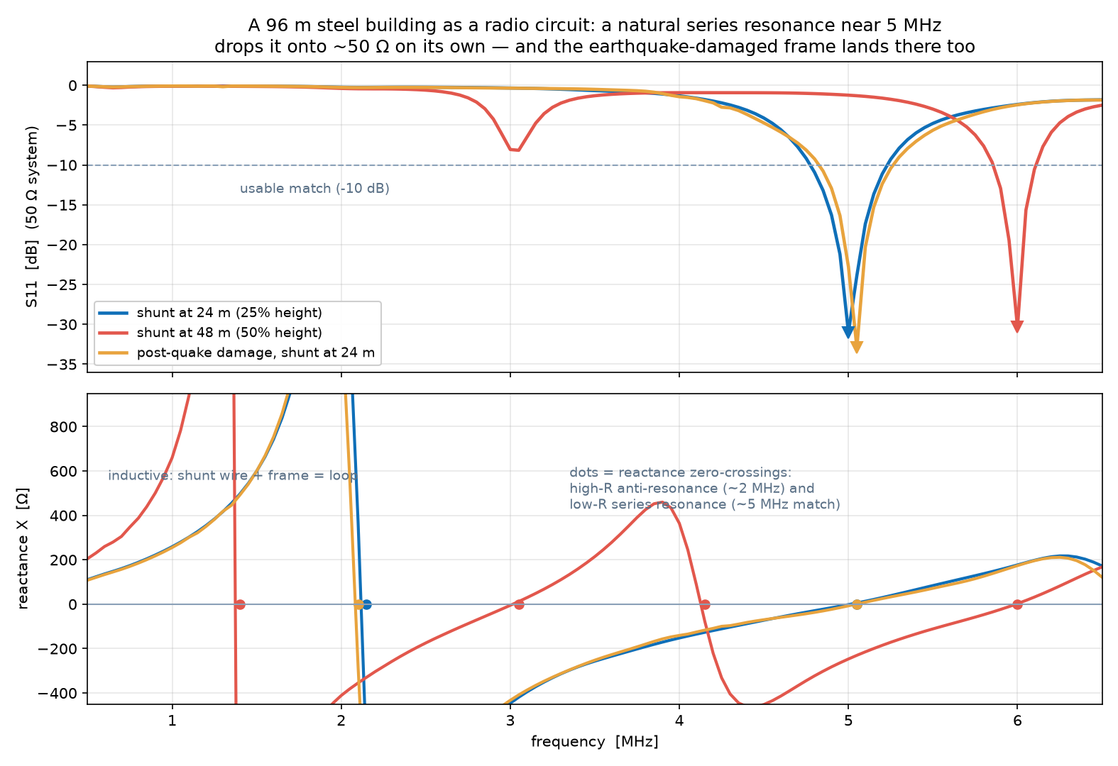
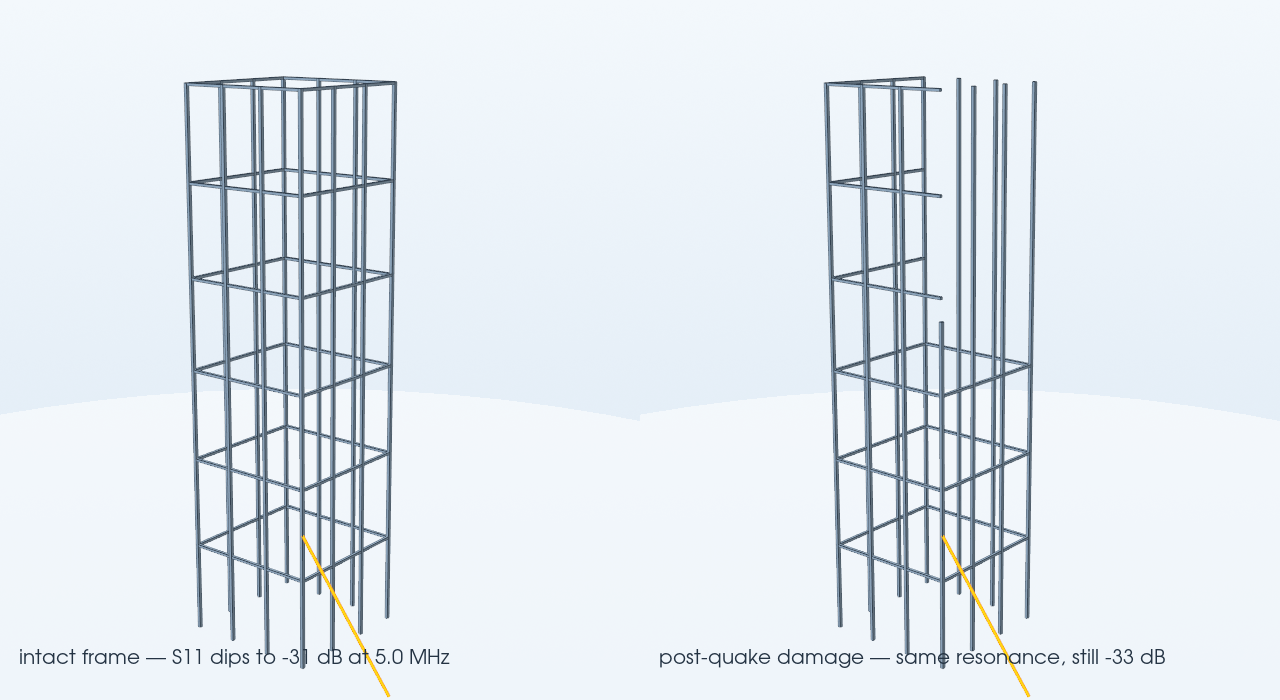
The frame is a 96 m tall, 24 × 24 m footprint steel skeleton — twelve perimeter columns with ring beams every 16 m, all structural steel (σ = 1.1 MS/m, μr = 100) — standing on a perfectly conducting ground plane inside a radiation box. The feed is a slant wire from a ground-level 50 Ω lumped port up to the frame, AM-shunt-feed style. Four Ansys HFSS driven-modal solves cover the design space: shunt attached at 24 m (25% of height), at 48 m, a post-earthquake damage state (all upper-half beams stripped from two faces and one corner column collapsed at 60 m), and a perfect-conductor control that isolates how much the lossy steel matters. Each case adapts its mesh at the 5 MHz operating frequency and then runs a 121-point discrete sweep from 0.5 to 6.5 MHz — every point an exact solve, the right choice for this electrically small, high-Q structure where an early interpolating sweep did not converge to physical (passive) results.
Is it right?
Four independent sanity anchors, none sharing code with the solve — all on the impedance, which is the quantity this model resolves well. First, the shape of the curve is the published shunt-fed-tower signature: inductive at low frequency (the slant wire and frame form a loop), a parallel anti-resonance, then a usable series-resonant match above it — the same signature documented for shunt-fed (folded-unipole) grounded towers in the standard references, the NAB Engineering Handbook’s treatment of AM tower feed systems and the ARRL Antenna Book chapter on shunt-fed grounded towers. Second, scaling: enlarging the shunt loop by moving the attachment from 24 m to 48 m drops the anti-resonance from 2.15 to 1.4 MHz — more loop, more inductance, lower frequency. Third, the perfect-conductor control: replacing lossy steel with an ideal conductor leaves the impedance almost unchanged (match resistance 50 vs 52 Ω, resonance at the same 5 MHz), proving the behavior is set by geometry, not material — the building's dimensions, not its metallurgy, are what tune it. Fourth, damage robustness: the resonance frequency and match depth barely move when two faces lose their upper beams, exactly what a low-Q, current-on-the-base radiator should do. One naive expectation deliberately fails: a 96 m mast "should" quarter-wave resonate near 0.8 MHz, but that formula is for a base-insulated series-fed mast; the shunt feed changes the circuit — which is precisely why it's the right way to drive a grounded building, and why the useful resonance lands up at 5 MHz instead.
The real-world connection
The 5 MHz match is a meaningful address: it sits by the 60 m band used for regional emergency communication, where near-vertical-incidence skywave bounces signals off the ionosphere and back down across a few hundred kilometers — no line of sight, no repeaters, terrain ignored. A grounded building that presents 50 Ω there, with no tuning network, is at least the right shape of tool for putting a damaged region back in contact. And the practical retrofit really is small: shunt-feeding needs a ground anchor, an insulated slant wire, and a coupling unit — hardware that fits in a van, which is why the technique has kept grounded broadcast towers on the air for ninety years. The building-scale lesson generalizes: any large grounded steel structure — water towers, stadium masts, bridge pylons — is a latent antenna waiting for a feed.
Want to know what a structure would do as a radiator before anyone builds or bolts anything? The same workflow — parametric structural geometry, full-wave HFSS solves across feeds, frequencies, and damage states — is the kind of simulation that answers "could it work?" before the field crew rolls. That's innovation through insight.