
In Space, Your Radiation Shield Is Secretly Your Thermostat
Roughly every 90 minutes, the skin of the International Space Station rides from about +120 °C in the sun to about −155 °C in Earth's shadow. There is no air up there to smooth anything out — no fans, no breeze, no convection at all. Every electronics box in orbit has to ride that same roller coaster. This study, suggested by community member Ryan Finelli, asks a question with a satisfying twist: when you armor a housing against space radiation, what does all that extra metal do to the heat? The answer is that the armor moonlights as climate control.
The physics: in vacuum, mass is memory
On the ground, electronics cool by convection — air carries the heat away, and a fan is a thermostat you can buy for three dollars. In orbit there is no air. A sealed housing has exactly two ways to move heat: conduction through whatever it touches, and thermal radiation to whatever it can see — which, for the sky-facing surfaces, is deep space at 3 kelvin. Heat leaves as εσT⁴, arrives as absorbed sunlight and the electronics' own dissipation, and the orbit switches the sunlight on and off like a metronome: about an hour of sun, then half an hour of shadow, forever.
Radiation shielding enters this story by accident. To protect components from the trapped-particle environment, designers thicken the aluminum walls — going from 2 mm to 8 mm raises the areal density from 0.54 to 2.16 g/cm², the kind of step published depth-dose curves associate with an order-of-magnitude cut in accumulated trapped-radiation dose (galactic cosmic rays, far more energetic, barely notice a few millimeters of aluminum). But that same metal is thermal capacitance: energy the box must gain or lose before its temperature moves. The heavy box remembers the sun through the eclipse and remembers the eclipse through the sun. Mass is memory.
Inside the model
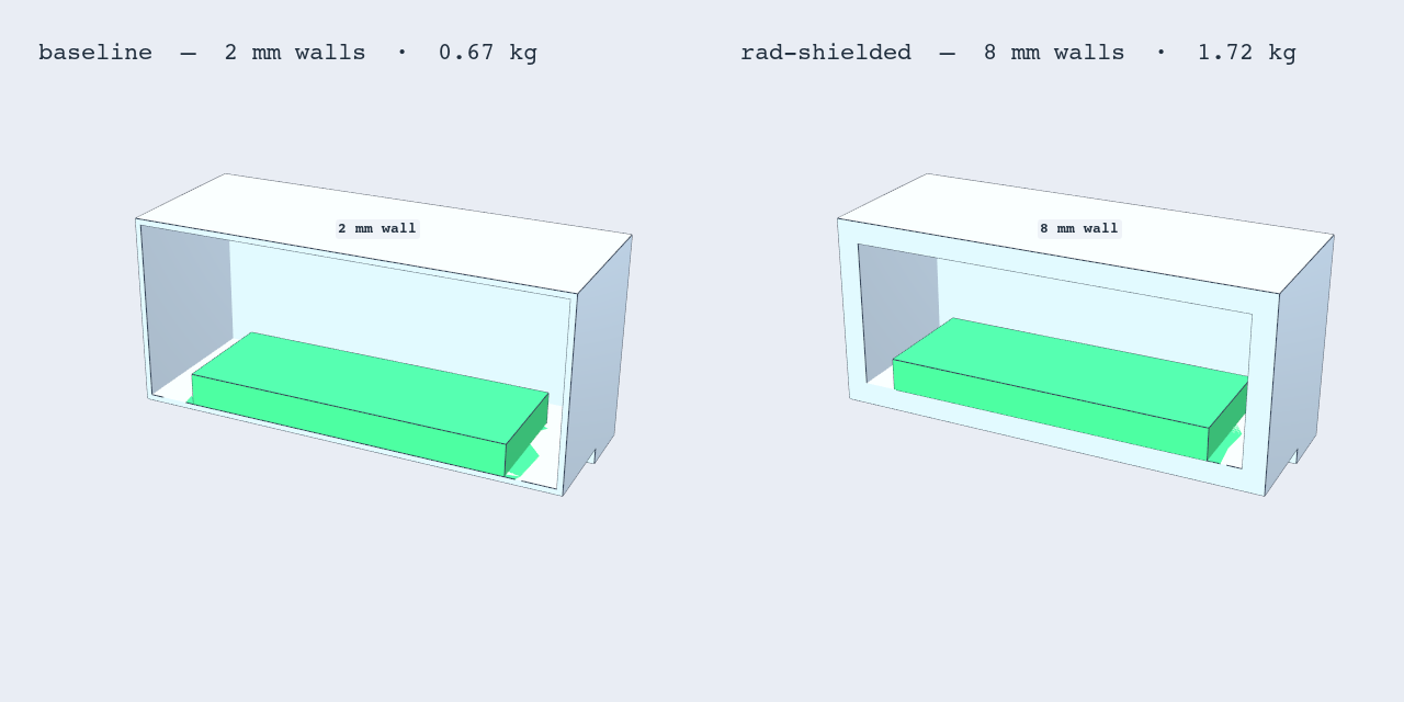
The housing is a 160 × 120 × 70 mm aluminum 6061 box with four corner mounting feet and a 120 × 85 mm electronics board bonded to the cavity floor, two ~10,000-node quadratic tet meshes. Three designs solve the identical mission: bare 2 mm walls (0.67 kg total), 8 mm armored walls (1.72 kg), and the 2 mm box under a suspended 1 mm foil shield (+60 g, 15 mm vacuum gap, coupled to the box top through a surface-to-surface radiation enclosure). The board dissipates a steady 12 W. The sun-facing top absorbs 817 W/m² (solar constant × gray-paint absorptivity 0.60) through a 60-minute sunlit arc, then nothing through a 35-minute eclipse, cycling for five 95-minute orbits. All external faces radiate to 3 K space with emissivity 0.85, and the feet sit on low-conductance isolators, so radiation is the only exit. The solver is Ansys Mechanical — steady-state thermal solutions for the hot and cold bounds, then a transient thermal run at 100 s steps (285 substeps) with the radiosity solver handling the T⁴ nonlinearity, and finally a static structural pass that imports the steady cold-bound temperature field — the permanent-shadow survival case — to load the bolted feet.
The other kind of radiation shield: thin metal and a vacuum gap
"Radiation shielding" means two different things in spacecraft engineering, and they get conflated constantly. The armor above is particle shielding — mass between electronics and trapped protons and electrons, where grams per square centimeter is the whole game. But thermal engineers use the same words for something nearly opposite: a thermal radiation shield — the thinnest possible sheet of metal, deliberately not touching anything, floating on a vacuum gap. Multi-layer insulation is a stack of dozens of them. (The famous Whipple shield — a thin sacrificial bumper standing off the hull — looks identical but is armor of a third kind, built to vaporize micrometeoroids and orbital debris; same architecture, different enemy.)
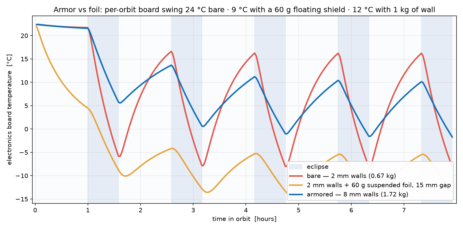
So we built one. Same 2 mm box, plus a 1 mm aluminum plate — 60 grams — suspended 15 mm above the sun-facing top. The physics does something lovely: the foil intercepts the full 817 W/m² and, having almost no thermal mass, simply rides the orbit — its own skin swings from +47 °C in the sun to −70 °C in eclipse, a 117 °C round trip every 95 minutes. It re-radiates roughly half of what it absorbs back to space, and hands the box below a far gentler, halved version of the solar cycle. In eclipse it works in reverse: the box's top face now sees the foil instead of 3 K deep space, so it cools more slowly. The result: the board behind the 60-gram foil swings just 8.7 °C per orbit — calmer than the kilogram of armor.
Before the foil wins the trade study, though, the honest fine print: shading your own top face also cuts the orbit-average solar input, so the foil variant settles about 14 °C colder overall (−14 to −5 °C) — in practice you would spend a watt or two of heater power, trim the shield coverage, or tune coatings to move the operating point back up. And the foil stops essentially zero particle dose — it solves a different problem than the armor. The two kinds of radiation shield are complements, not competitors: real spacecraft carry both.
How the radiation was modeled
All three variants run in Ansys Mechanical's radiosity solver, with two radiation formulations doing different jobs. Surfaces that see only deep space get a radiation-to-ambient boundary — emissivity times σ(T⁴ − Tamb⁴) against a −270 °C ambient, no view factors needed. The vacuum gap is different: the foil's underside and the box's top face exchange with each other, so they are paired in a surface-to-surface open enclosure — the solver computes the view factors between the two faces, and the "open" setting lets whatever energy escapes past the plate edges go to the 3 K ambient instead of being forced back in. Every surface here is gray and diffuse at ε = 0.85 (ordinary paint) — deliberately conservative, because real radiation shields cheat harder: polish the facing surfaces to ε ≈ 0.05, as MLI does, and the gap's insulation improves by another order of magnitude. That, plus stacking layers, is the obvious next experiment.
Mechanical is the right tool for this housing-level question, and it is not the only door into the problem: Ansys Icepak brings the same vacuum radiation physics with electronics-native detail (component powers, board conduction layers), Fluent's S2S and discrete-ordinates models extend to complex multi-surface enclosures, and Ansys Sherlock turns the temperature cycles solved here directly into solder-joint fatigue life for the boards riding inside. The same orbit, examined at four altitudes of detail.
Is it right?
The control here is a closed-form model that shares no code with the FEA. A radiating box in equilibrium must satisfy εσAT⁴ = Qin: with 27.7 W absorbed in the sun that predicts a +20.2 °C hot bound, and with 12 W in permanent shadow, −35.2 °C cold — Mechanical's steady solutions land within about 1.5 °C of both. The transient's headline number has its own independent check: a lumped-capacitance model (mC = 675 vs 1,608 J/K, radiative time constants 40 vs 96 minutes) predicts the shielded box should swing about 1.9× less per eclipse; the full solve delivers 2.05×. The hand model deliberately validates the ratio, not the absolute swings — starting each eclipse from the steady hot bound, it over-predicts both amplitudes by 30–40% in a way that largely cancels between variants. Two models, one from first principles on a napkin, one from a 10,000-node radiosity solve — agreeing within 8% on the number the study is about.
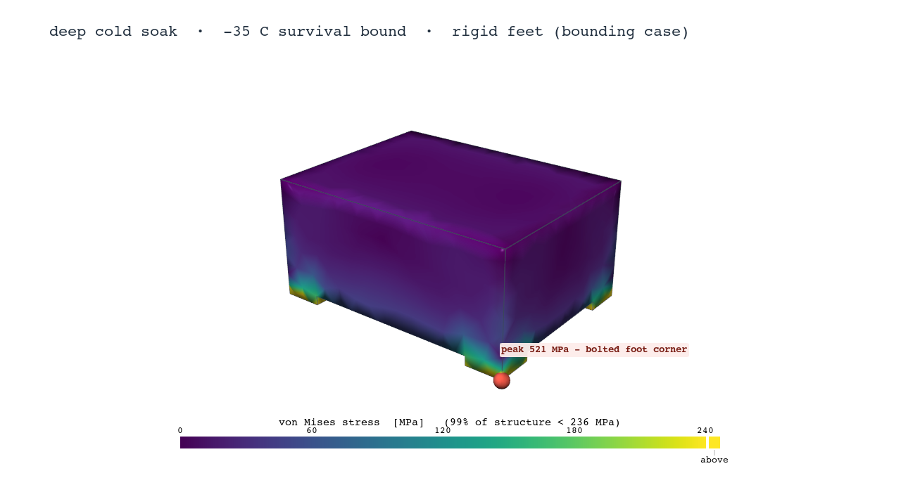
That stress picture is why real flight boxes mount on compliant isolators or slotted feet: bolt an aluminum box rigidly to a cold structure and the contraction alone overwhelms the corner joints — a linear model pushing past yield at the bolts means a real joint would locally yield or slip on the very first deep soak. A simple full-constraint estimate, EαΔT ≈ 92 MPa, sets the membrane floor; corner bending carries the 99th-percentile roughly 2.6× above it (236 vs the 92 MPa floor). And here is the trade hiding in the good news: the shielded box loads its mounts about 40% harder than the thin one (236 vs 169 MPa at the 99th percentile), because thicker walls fight the constraint more stiffly. The shielding that calms the electronics stresses the mounts — thermal design giveth, structural design pays.
The real-world connection
Thermal engineers buy temperature stability four ways: heaters (cost power), radiator sizing (cost area), phase-change or loop devices (cost complexity), and plain thermal mass (cost launch weight). What this study shows is that when the radiation environment already forces mass into the walls, that fourth lever comes free — the shield you bought for dose protection is quietly doing thermostat duty. It is one of the happier coincidences in spacecraft design: the same kilogram serves two subsystems. Crystal oscillators drift with temperature, batteries age with every deep cold excursion, and solder joints accumulate damage with each thermal cycle — so halving the swing amplitude is not a comfort feature, it is a reliability multiplier.
Want to know what an orbit does to hardware that matters? The same workflow — parametric geometry, transient thermal with radiation, and a thermal-stress handoff, end to end in Ansys Mechanical — is the kind of simulation that finds the design that survives before anything flies. That's innovation through insight.