
Newton’s Cradle, But With Bowling Balls
Someone in the Ideas Lab asked the question every desk-toy owner eventually wonders about: what if the little steel balls were bowling balls? We took two 7 kg steel spheres — one hanging at rest, one swung into it at a brisk walking pace, exactly like a two-ball Newton’s cradle — and simulated the click. It turned into a small lesson in picking the right solver, because the first tool we reached for got the stress beautifully and the bounce completely wrong. So we ran it twice.
The physics: a collision is a very fast spring
When two hard spheres touch, they don’t meet at a point — each flattens by a fraction of a millimeter and shares a small circular contact patch that behaves like an extremely stiff spring. It compresses, stores the kinetic energy, and pushes back. For elastic spheres the whole handshake is described by Hertzian contact theory, worked out in 1882 and still the reference every contact solver is checked against. It predicts the contact-patch size, the peak pressure, and how long the bodies stay in contact — all from the radii, the stiffness, and the closing speed.
Our spheres are 119.4 mm across (about a five-pin bowling ball) and weigh 6.997 kg each in steel. One hangs at rest; the other arrives at 1.401 m/s. No gravity, no supports in the model — just the moment of contact between two free bodies.
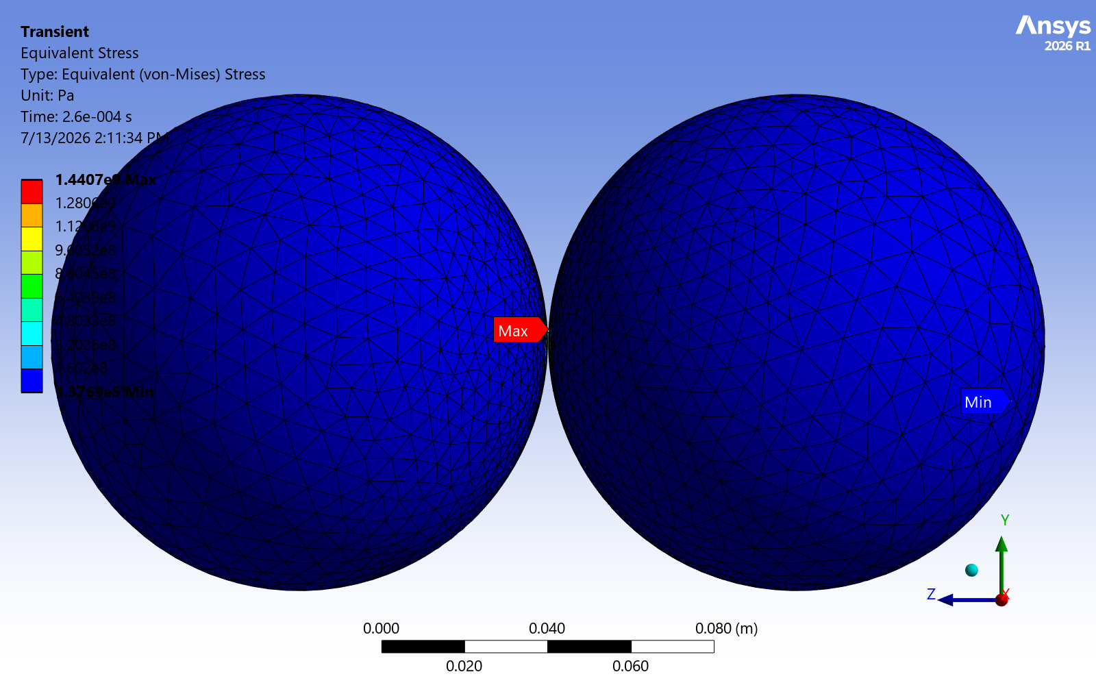
Inside the models
Two solid steel spheres (E = 200 GPa, ν = 0.3, ρ = 7850 kg/m³). We solved the same collision two ways: an implicit transient structural analysis in Ansys Mechanical (about 15,500 elements, frictionless contact, 360 fixed sub-steps) for the detailed contact stress, and an explicit dynamics analysis in Ansys LS-DYNA (a structured 8,200-hex mesh, automatic surface-to-surface contact) for the collision and bounce. Same geometry, same speed, same material — two formulations built for different jobs.
Is it right? Check it against Hertz
This is the part that decides whether a contact model can be trusted. Hertz theory gives closed-form answers for this exact problem, so we can put the simulation next to hand calculation:
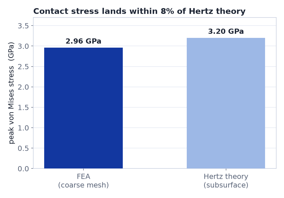
The agreement is good and it is honest: our findings are consistent with Hertz on peak stress (2.96 vs 3.20 GPa), the theory puts the contact patch at a 2.2 mm radius and the peak contact pressure at 5.2 GPa, and the bodies stay in contact for only about 340 µs. The contact mechanics a designer would need are reproduced — which is what a transient structural solver is built to do.
Same collision, two solvers — and they disagree
Here is the part worth more than any single number. We expected the implicit solver to hand the velocity cleanly from the striker to the target and let them part — the classic click. It didn’t. It kept trading the velocity back and forth. The explicit solver did exactly what a cradle does. Side by side:
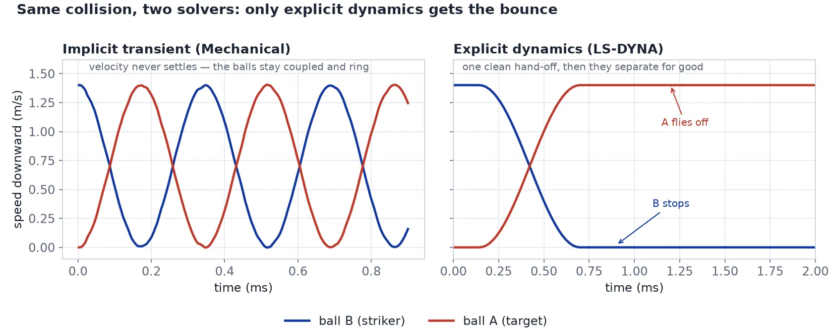
Two truly free balls can collide only once; after the hand-off they drift apart and never meet again. The implicit transient kept them coupled because that is how it is built — it holds a contact through its equilibrium iterations and has no free-flight separation mode, so an undamped elastic pair simply rings. Energy is conserved either way (the model has no damping), so nothing is wrong with the implicit answer — it is a physically consistent answer to a slightly different question. The explicit solver integrates the actual dynamics, lets the contact open, and delivers the bounce.
The lesson is a tool-selection one: implicit structural is the right tool for the contact stress and the wrong tool for the bounce. A rigid-body collision train — the actual “how many clicks” question — belongs in explicit dynamics. Matching the physics to the solver, not the other way around, is most of the job.
So how many clicks?
Our explicit model is perfectly elastic (restitution 0.9999), which means in the idealized case it would ring almost forever — the clean transfer just moves down the line. A real cradle dies because of losses this model deliberately omits: material damping, micro-plasticity at the contact, and sound (that’s the click you hear leaving as energy). Hardened steel returns roughly 90–95% of impact energy per collision in practice. Starting from that literature figure — not from this simulation — a swinging steel cradle would give on the order of a couple of dozen audible clicks before the swing fell below what you’d hear. Treat that as a back-of-envelope estimate; the honest simulation results here are the contact stress (vs Hertz) and the clean elastic momentum transfer (LS-DYNA).
Want the contact stresses in your own assembly answered properly — with the right solver for the job? The same Ansys workflow — a validated contact model, checked against theory, and the physics matched to the tool — is the kind of workflow that helps teams size press-fits, bearings, gear teeth, bolted joints and impact events. Innovation through insight.