
Why Your Phone Throttles in the Sun
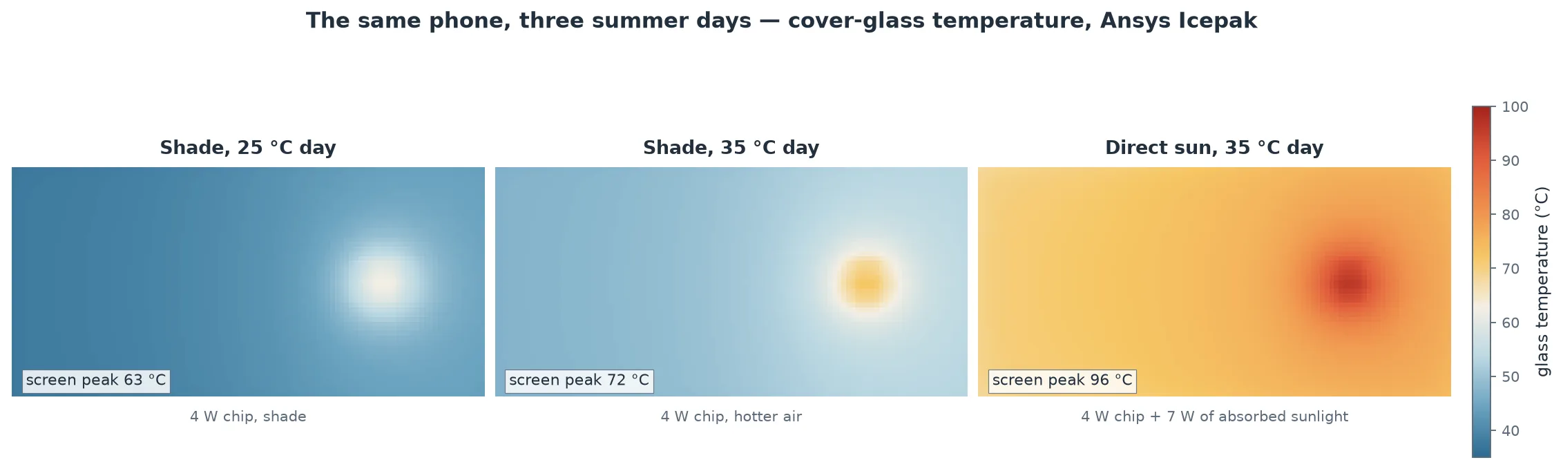
You are filming your kid's soccer game on a bright afternoon, and after four minutes the video app quietly drops from 4K to 1080p and your phone gets warm and sluggish. Step into the shade and, a minute later, it perks back up. Nothing is broken. The chip inside just hit a temperature limit and pulled its own power back to save itself — and the deciding factor was not the game, it was the sunlight landing on the glass. We built a simplified phone in Ansys Icepak and let it heat up in the shade and in direct sun to watch exactly where the line gets crossed. The solve is steady-state, so it pins the hot and cool endpoints the phone settles into — not the minute-by-minute clock in that opening scene.
The physics: a chip has nowhere to send its heat
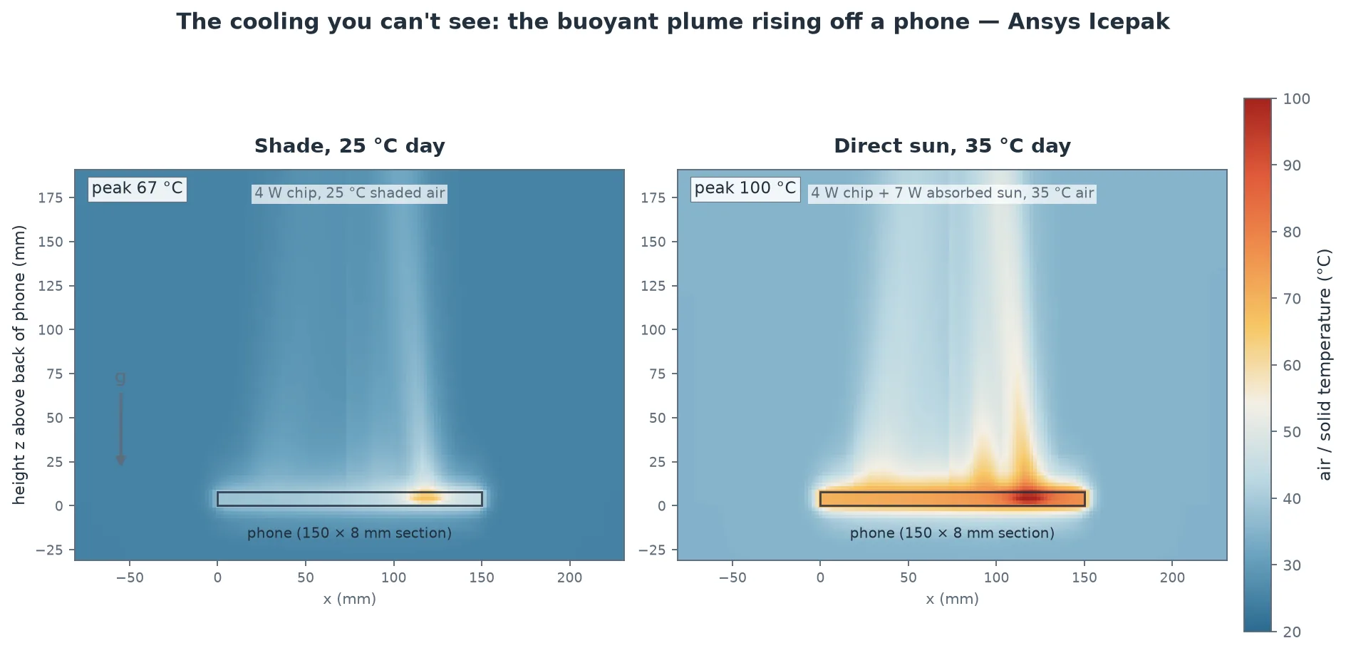
A phone has no fan and no vents. Every watt the processor burns has to crawl out through the body of the phone — conducting sideways through the board and the aluminum chassis, spreading across the glass and the back — and then leave the outer surfaces two slow ways: natural convection, where air warmed by the phone drifts upward and is replaced by cooler air, and thermal radiation, the infrared glow every warm surface gives off. Both are weak. Together they set a hard ceiling on how many watts the phone can shed while keeping the silicon below its limit.
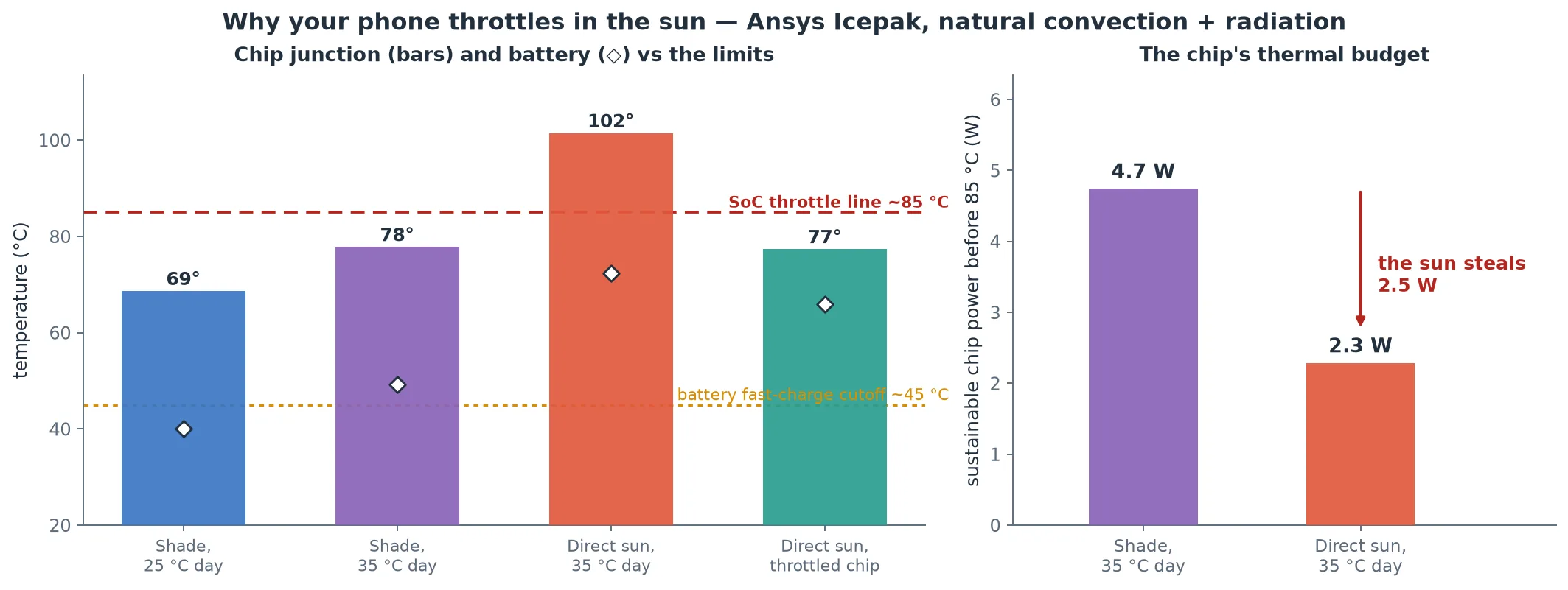
Now point the glass at the sun. Sunlight at midday delivers about a kilowatt per square meter, and a dark phone face absorbs most of it. On our phone's palm-sized front that is 7.0 W of absorbed heat — poured onto the same surface that was supposed to be shedding the chip's heat. The cooling path now has to carry the chip's own watts plus the sun's, through the same feeble convection and radiation. The surfaces run hotter, the inside runs hotter, and the junction climbs until the chip's thermal governor trips and throttles the clock speed to cut its own power. That is the sluggishness you feel.
Inside the model
The phone is a 150 × 72 × 8 mm slab built the way a real one stacks up: an aluminum back, a lithium-ion battery, an FR-4 circuit board, a 12 × 12 mm silicon SoC dissipating 4 W under load, an effective-conductivity filler standing in for the rest of the guts, and a cover glass on top — each with its own conductivity, density, and specific heat. It hangs in open air (a vent-mount idealization) so air can rise freely off every face. Ansys Icepak solved the conjugate problem — conduction inside the solids coupled to buoyant airflow around them — as a steady natural-convection case with gravity on and a Discrete-Ordinates radiation model (surface emissivity 0.8), on a 89,015-cell mesh, four cores, about two minutes per run. Direct sun is added as 7.0 W of absorbed power spread over the glass face; the “throttled” case simply drops the chip to 1.5 W to mimic the governor pulling back.
Is it right? A napkin calculation gets the outside temperature
The believable part is not the picture; it is that the phone's skin temperature matches a calculation you can do by hand. Treat the phone as an isothermal slab losing heat by textbook natural-convection correlations (the classic Nu = 0.54/0.27/0.59 Ra1/4 plate laws for a hot top, bottom, and sides) plus radiation at emissivity 0.8, and solve the energy balance for the surface temperature. Across all four cases that pencil-and-paper shell temperature lands within 9% of what Icepak computes — comfortably inside the honest 10–20% band these correlations carry. That agreement on the outside is the reason to trust what the solver says about the inside.
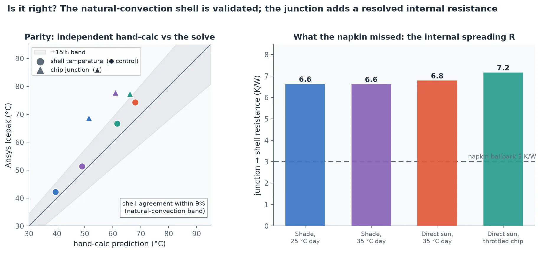
Two more checks fall out for free. Raising the ambient air by 10 °C in the shade (25 → 35 °C) lifts the junction by about 9 °C — the near-one-to-one shift you expect from a roughly linear system. And the junction rises in step with chip power at a steady 9.6 °C per watt between the two sun runs, which is exactly the slope that turns the 85 °C ceiling into a sustainable-power budget in the chart above.
Why it matters: the sun sets the limit, not the app
Every summer complaint about a “slow” phone traces back to this balance. The camera app that overheats in minutes outdoors but runs for an hour indoors is not buggy — the outdoor sun has eaten most of its thermal headroom before you even press record. Charging in a hot car trips the battery's own ~45 °C guard for the same reason, which is why phones refuse to fast-charge when warm. And it is why phone makers spend real engineering on graphite spreaders, vapor chambers, and lighter-colored or more reflective backs: with no fan, the only levers are spreading the heat over more area and shedding it a little faster. Our model shows why those levers matter so much — in the sun, a few watts of margin is the whole game.
It is also a small lesson in system thinking. The chip vendor's spec sheet says 4 W is fine; the phone in the shade agrees; the phone in the sun does not. The component was never the limit — the environment plus the enclosure was. That is the question a thermal simulation answers before a product ships.
Designing anything that has to stay cool without a fan — a phone, a sealed outdoor enclosure, an LED fixture, a ruggedized sensor, a battery pack in the sun? The same Ansys Icepak workflow — geometry, a conjugate natural-convection-plus-radiation solve, and junction temperatures checked against the physics — is how simulation answers “how hot, and when does it throttle” before the plastic is tooled. That's innovation through insight.