
How Thick Does Lake Ice Need to Be to Drive a Truck On It?
Every winter, ice-road crews on northern lakes drill a hole, measure the ice, and make a bet with physics: is this sheet thick enough to hold a truck? Get it wrong and the truck goes through — a genuinely deadly mistake that the History Channel built a whole show around. The old field rule of thumb is "twelve inches for a medium truck," but where does that number come from? Suggested by community member IceRoadTruckers, we put a floating ice sheet into Ansys Mechanical to watch a pickup make its bowl — and to see how close the physics comes to the rule that keeps drivers alive.
The physics: ice floats, so it bends on a spring
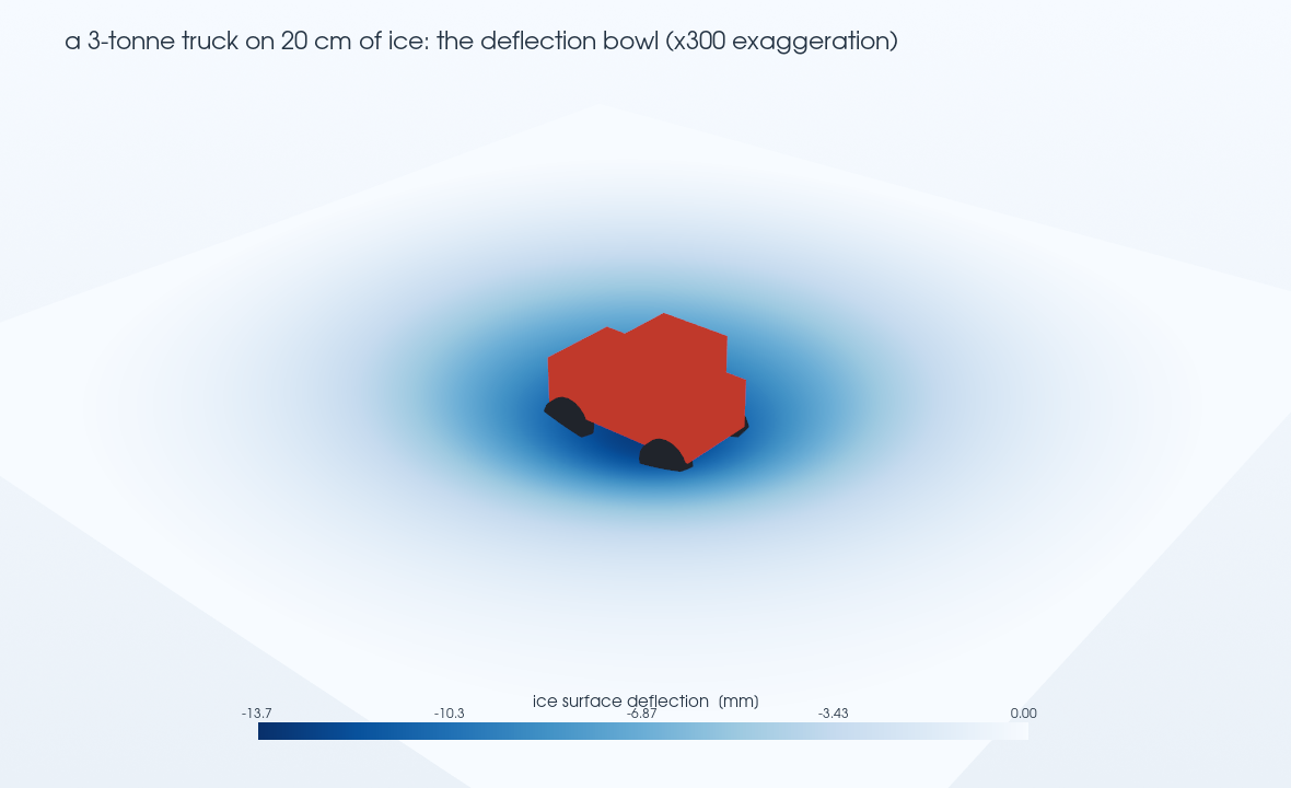
A floating ice sheet is a textbook thin elastic plate on an elastic foundation. The "foundation" is the water: push the ice down by one millimeter and buoyancy pushes back with the weight of the water displaced — a distributed spring of stiffness k = ρwg ≈ 9,810 N/m³ under every square meter. A wheel load doesn't punch through locally; it presses the whole neighborhood into a shallow dish, and the ice fails not by crushing but by bending — it cracks in tension on the underside, at the bottom of the bowl, when the flexural stress exceeds the strength of the ice (about 0.7 MPa for lake ice by the usual design value).
The size of that dish is set by a single number, the characteristic length ℓ = (D/k)1/4, where D is the plate's flexural rigidity. For 20 cm ice, ℓ ≈ 5 m — larger than a pickup's 3.7 m wheelbase, and that turns out to matter a lot.
Inside the model
The ice is a 50 × 50 m plate meshed with 40,000 shell elements (E = 9 GPa, ν = 0.33), floating on a Winkler elastic foundation of stiffness k = ρwg to represent buoyancy. The truck is a loaded 3-metric-ton pickup — four 7.4 kN wheel loads on 18 cm contact patches, at a 3.7 m wheelbase and 1.7 m track. We swept the ice thickness from 10 to 40 cm, and separately marched the truck across the sheet in 17 steps to film the bowl. The solver is Ansys Mechanical (MAPDL, plate-on-elastic-foundation formulation — the fast, exact way to do a floating sheet).
Is it right?
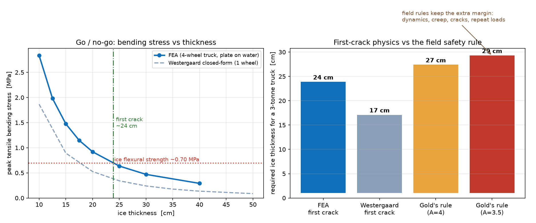
Three references, none sharing code, bracket the answer and explain each other. The classic Westergaard closed-form for a single wheel on a plate-on-elastic-foundation predicts first crack at ~17 cm. Our FEA, with the whole four-wheel truck, says ~24 cm — thicker, and that difference is the physics the closed-form misses: the wheels are closer together than the 5 m bowl, so their dishes superimpose and the ice works harder than a one-wheel formula admits. Then the field rule — Gold's formula, P = A·h², the empirical bearing law used by ice-road engineers — asks for ~27–29 cm for this truck, i.e. the famous "twelve inches." So the numbers line up in a sensible ladder: naive single-wheel 17 cm → real four-wheel FEA 24 cm → field-safe rule ~30 cm. The simulation lands right where it should, between the idealized physics and the margin-loaded rule that keeps trucks out of the water.
Does the contact patch matter?
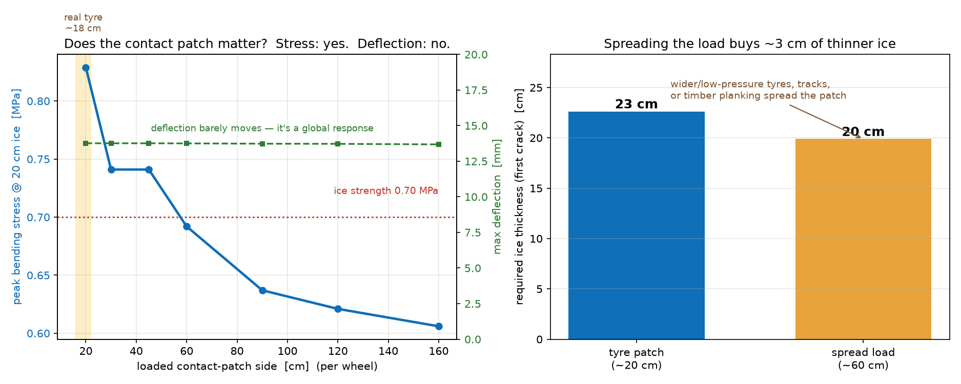
A sharp question came back on the first pass: the wheels press on small patches — would making them smaller change the answer? We re-ran on a finer mesh and swept the loaded patch size, and the split is instructive. The deflection barely budges — 13.7 mm whether the load is spread over 20 cm or 1.6 m — because the dish is a global response to total weight and buoyancy, blind to how the load is spread. The peak bending stress does the opposite: concentrate the load and it climbs (0.83 MPa for a tire-sized 20 cm patch, down to 0.61 MPa spread over 1.6 m). Since ice cracks on stress, the required thickness follows — a tire-sized patch first-cracks at ~23 cm, a load spread to 60 cm at ~20 cm. That ~3 cm (over an inch) is exactly why ice-road practice spreads loads: wide low-pressure tires, tracks, and timber planking under heavy gear all trade a smaller footprint for thinner survivable ice. It also confirms the headline — the properly-resolved tire patch lands at ~23 cm, within a centimeter of the ~24 cm from the coarser first model.
The real-world connection
Here is the part that surprises people: ice roads have a posted speed limit, and it isn't about traction. Our model is static — it finds the bowl for a truck sitting still or rolling slowly. But a moving load makes waves. The bowl is really a depression riding on the water beneath the ice, and the water can carry flexural-gravity waves at a certain speed set by the lake depth. Drive near that critical speed — often only 25–40 km/h in shallow water — and the truck's bowl resonates with its own wake, deflections pile up, and ice that would easily hold the parked truck can crack under the moving one. That's why the Northwest Territories and Baltic ice roads post slow limits and forbid two trucks from passing: it's resonance control. Capturing that properly is a coupled hydroelastic problem — the ice sheet plus the moving water inertia — and it's the natural next step from this static baseline.
Want to know whether a structure will hold a load before you bet on it? The same workflow — the right idealization, a fast parametric sweep, and validation against independent references — is the kind of simulation that turns a rule of thumb into a number you can defend. That's innovation through insight.